Lianxu Zhou^a, Xiaowei Wang^{a,b}, Aijun Ye^{a,*}
^a State Key Laboratory of Disaster Reduction in Civil Engineering, Tongji University, 1239 Siping Rd., Shanghai 200092, China
^b College of Civil and Transportation Engineering, Hohai University, 1 Xikang Rd., Nanjing 210024, China
ARTICLE INFO
Keywords:
Low cycle fatigue
Transverse steel damper
Shake-table test
Ground motion sequence
ABSTRACT
The low cycle fatigue performance of metallic hysteretic dampers is widely concerned by researchers because the energy-dissipation mechanism of these dampers primarily relies on inelastic deformations of metals. To examine the low cycle fatigue performance of a metallic hysteretic damper for bridges, called the Transverse Steel Damper (TSD), shake-table tests are conducted on a 1/35-scaled cable-stayed bridge model installed with two types of TSDs with different yield strengths, and the bridge model is subjected to a series of ground motion sequences including pulse- and non-pulse-like ground motions. After that, the post-earthquake capacities of TSDs are further examined using monotonic quasi-static tests and compared with their pre-earthquake capacities. Then, three theoretical methods in the literature, two of which are improved in this study, are used to assess the fatigue performance of TSDs. The results indicate an excellent low cycle fatigue performance for TSDs, which experienced more than ten strong shakings and almost remained the original performance without any fatigue failure.
1. Introduction
In the last few decades, the concept of structural damage control has attracted wide attention from both academic and engineering communities. The goal of this concept is to limit the earthquake-induced damages to specific components such as energy dissipation dampers for the purpose of protecting super- and sub-structures. Under this background, a large number of damping devices especially passive dampers, including viscous dampers, viscoelastic dampers, friction dampers, and metallic hysteretic dampers, etc., have been widely used in bridge engineering and structure engineering 1,2,3,4 due to their easy construction and convenient implementation. Among these passive dampers, the metallic hysteretic dampers that dissipate seismic energy through inelastic deformations of metals have been proved to be superior in economy, durability, and reliability 5,6,7. Since Kelly et al. 8 put forward the concept of energy absorption using metallic dampers in 1972, a variety of metallic hysteretic dampers were proposed and studied by researchers through experiments and/or numerical simulations. According to the yielding mechanism, these hysteretic dampers can be generally categorized into four types, including the bending-type such as steel plate/bar energy dissipation devices 9,10,11,12,13, the axial compression-tension type such as Buckling Restrained Braces (BRBs) 14, the shear-type such as Shear Panel Dampers (SPDs) 15, and the torsion-type such as torsional beams 16.
Recently, Shen et al. 17 developed a bending-type device called the Transverse Steel Damper (TSD), which adopts triangular steel plates as energy-dissipation components, for the transverse seismic mitigation of cable-stayed bridges. The TSDs can freely accommodate the longitudinal movement of bridge decks under service condition loads. This unique property distinguishes TSDs from existing bending-type devices. The authors have performed a series of quasi-static and shake-table tests and associated numerical analyses to verify the excellent dissipation capacity of TSDs 17,18. A noted limitation in the previous studies is the lack of experimental verification on the low cycle fatigue performance of TSDs, which provides the motivation for the current study.
Since the energy dissipation mechanism of metallic hysteretic dampers primarily relies on inelastic deformations of metals, their low cycle fatigue issues have been concerned by many researchers 19,20,21,22,23. In particular, multiple strong aftershocks may occur shortly after a destructive main shock 24. For example, the 2015 Nepal earthquake witnessed seven sequential strong motions (moment magnitude, M_w > 5.3) near Gorkha from April 25 to 27 25. Also, in the 2016 Kumamoto earthquake, three strong shakings (M_w > 6) occurred on Kyushu Island within only three days 26,27. Therefore, dampers in bridges located in these seismic-prone areas may experience multiple excitations during their service lives. Under such frequently sequential shakings, in general, there is no opportunity to repair or replace those impaired dampers in gaps between these shakings. Therefore, an excellent and reliable low cycle fatigue performance should be possessed by metallic hysteretic dampers.
There are a few requirements for the low cycle fatigue performance of metallic hysteretic dampers in various seismic design specifications. For example, the American Institute of Steel Construction (AISC) stipulates that BRBs should sustain cumulative inelastic axial deformations at least 200 times their yield deformations 28. In Chinese specifications 29, an index called Equivalent Hysteretic Cycles (EHCs), which should not be less than 30, is used to assess the low cycle fatigue performance of metallic dampers. Aside from these stipulations, some notable research has focused on the low cycle fatigue issues of metallic hysteretic dampers in recent years 14,30,31,32. For example, Usami et al. 14,23 and Wang et al. 32 investigated the low cycle fatigue performance of BRBs under variable and constant strain amplitudes using quasi-static tests, and they pointed out that the BRBs installed in structures should withstand strong earthquakes three times without replacement. In their studies, an index named Cumulative Inelastic Deformation (CID) was adopted to assess the low cycle fatigue performance of BRBs, and 0.7 is recommended as the ultimate value of CID for BRBs. Xu et al. 33 investigated the low cycle fatigue performance of low-yield-point SPDs using reversed cyclic loading quasi-static tests. Camara et al. 34 theoretically evaluated the low cycle fatigue performance of a bending-type device using a strain-based method. In short, existing studies mainly focus on the low cycle fatigue performance of axial compression-tension-type (e.g., BRBs) and shear-type (e.g., SPDs) metallic hysteretic dampers using quasi-static load-patterns, while relatively few experimental studies focus on the low cycle fatigue performance of bending-type metallic hysteretic dampers such as TSDs. Moreover, the real scenario of dampers experiencing ground motions can be better reproduced by shake-table tests. Therefore, it is a better way to assess low cycle fatigue performance than conventional quasi-static tests.
This paper aims to examine the low cycle fatigue performance of TSDs using shake-table tests. Two sets of TSDs with different yield strengths are separately installed on a 1/35-scaled cable-stayed bridge model, which is subjected to ground motion sequences in the Multifunctional Shaking Table Lab at Tongji University, Shanghai, China. After that, the post-earthquake capacities of the tested TSDs are assessed using monotonic quasi-static tests. Then, the abovementioned three theoretical methods, including the strain-based, the CID-based, and the EHC-based methods, together with the assistance of numerical simulations, are adopted to assess the low cycle fatigue performance of TSDs.
2. Test Program
2.1. Descriptions of Shake-Table Tests and TSDs
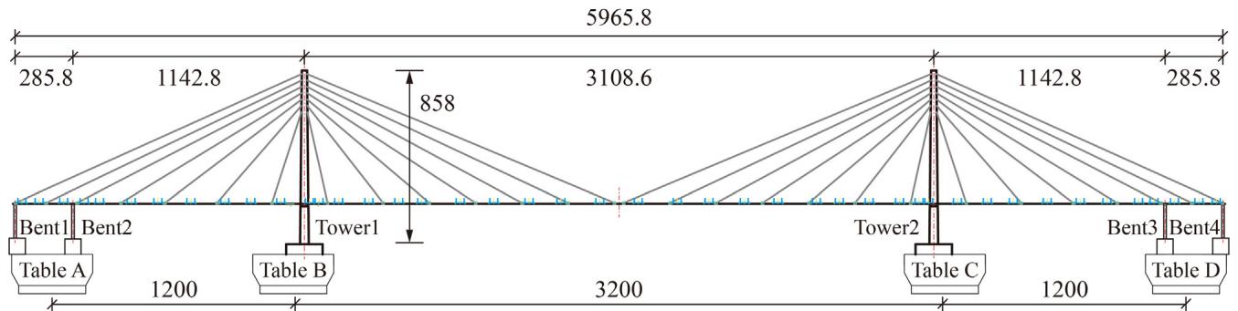
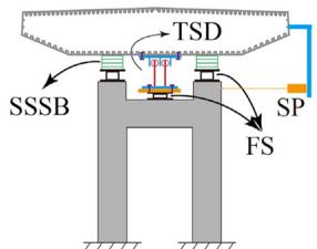
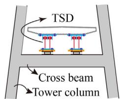
A 1/35-scale model of the Sutong Bridge (a cable-stayed bridge with a main span of 1088\text{m})was designed. Fig. 1 schematically shows the layout of the shake-table test and configurations of deck-bent and deck-tower connections. As shown in Fig. 1(a), the total length of the test model is 59.66\text{m} and the height of towers is 8.58\text{m}. Four shake-tables (A to D) are used in the test. Bents 1 and 2 are mounted on Table A, and Tower 1 is mounted on Table B. Fig. 1(b) and (c) shows deck-bent/tower connections. One TSD is placed at each deck-bent connection in parallel with two sliding spherical steel bearings, while two TSDs are installed at each deck-tower connection.
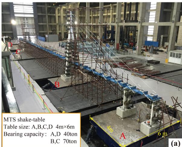
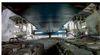
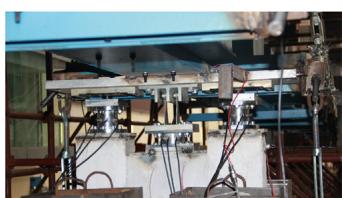
Fig. 2 presents the full view of the test model and the detailed deck-bent/tower connections. The TSD located at Bent 2 is selected as the main research object. The displacement of the TSD was measured by a string potentiometer. Additionally, tri-axial force sensors were placed at the bottoms of the TSD to measure horizontal forces transferred from the deck to bents and towers.
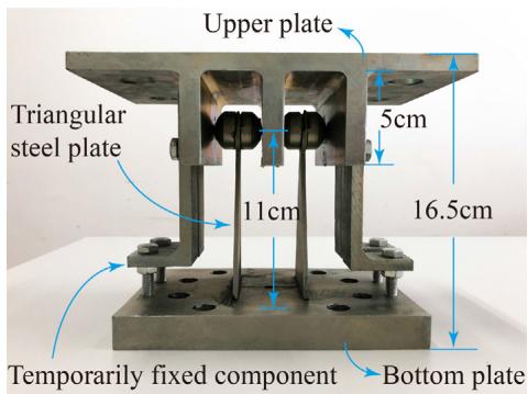
Fig. 3 presents the detailed configuration of the tested TSD. One TSD consists of two parallel triangular steel plates, each with a width of 7\text{cm}, a height of 11\text{cm}, and a thickness of 0.3\text{cm}. To examine the low cycle fatigue performance of TSDs with different yield strengths, two sets of TSDs (named TSD-1 and TSD-2) are installed separately. The yield strengths are 326\text{MPa} and 193\text{MPa} for TSD-1 and TSD-2, respectively. Table 1 lists the geometric parameters.
2.2. Properties of TSDs
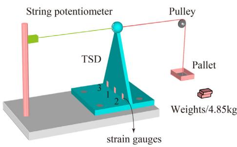
To obtain mechanical parameters of the studied TSDs, quasi-static tests were carried out on samples of TSD-1 and TSD-2. As schematically shown in Fig. 4, a simplified monotonic loading device is designed. The horizontal displacement at the plate top is monitored by a string potentiometer. In this paper, the design displacement of TSD-1 and TSD-2 is 4.7\text{cm}.
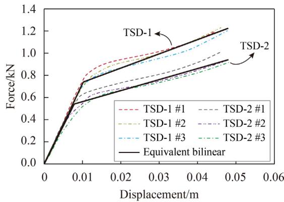
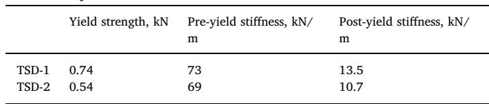
Fig. 5 shows the global force-displacement curves of TSD-1 and TSD-2. The mechanical parameters are listed in Table 2.

2.3. Ground Motions and Loading Scheme
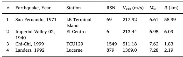
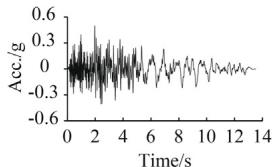
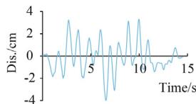
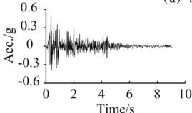
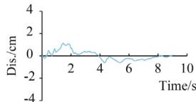
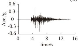
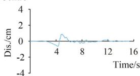
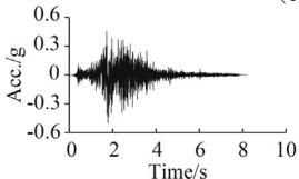
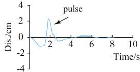
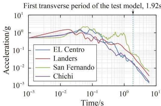
Four ground motions are selected from the PEER-NGA database 35: #1 San Fernando, #2 El Centro, #3 Chi-Chi, and #4 Landers. Table 3 lists the information of these records. Fig. 6 displays the time-compressed ground motions scaled to a PGA of 0.5g.
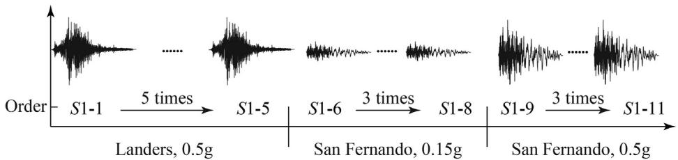
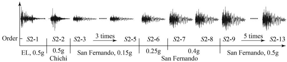
Two synthetic ground motion sequences are adopted. Sequence S1 (Fig. 8) consists of 0.5g Landers (5 times), 0.3g San Fernando (3 times), and 0.5g San Fernando (3 times). Sequence S2 (Fig. 9) comprises 0.5g El Centro, 0.5g Chi-Chi, and San Fernando with gradually increased PGA. S1 and S2 were adopted for the cases with TSD-1 and TSD-2, respectively.
3. Test Results
3.1. Displacement Response and Hysteretic Behavior of TSDs
Fig. 10 presents the seismic responses of TSD-1 under sequence S1. A gradually increasing trend is observed in the residual displacements. Stable and nearly coincident hysteretic curves of TSD-1 under the last two shakings (S1-10 and S1-11) are recorded, indicating no fatigue failure.
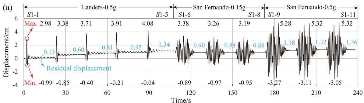
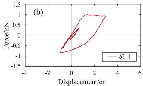
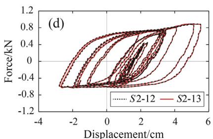
Fig. 11 shows the seismic responses of TSD-2 under sequence S2. Similar stable hysteretic curves are recorded under the last two shakings (S2-12 and S2-13), indicating no fatigue failure.
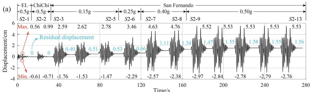
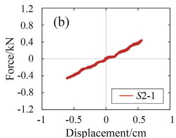
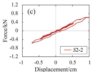
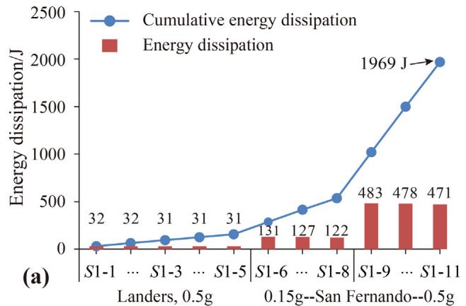
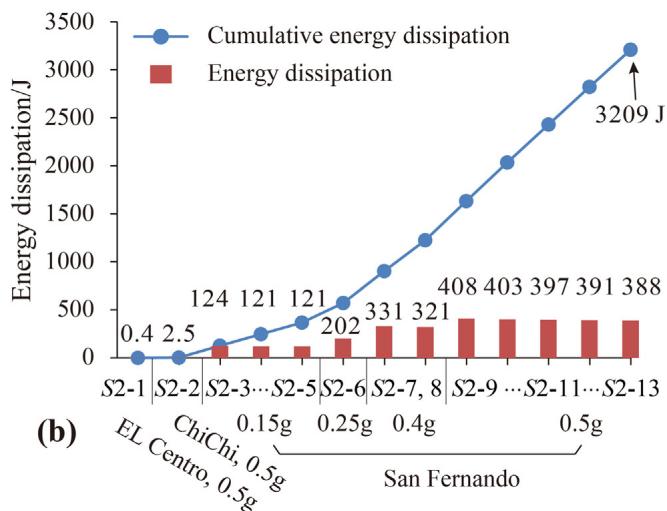
Fig. 12 quantifies the dissipated energy. Considerable differences in dissipated energy are detected among ground motions despite the identical PGA of 0.5g, suggesting that PGA is not an optimal intensity measure for predicting energy dissipation.
3.2. Post-Earthquake Observation of TSDs
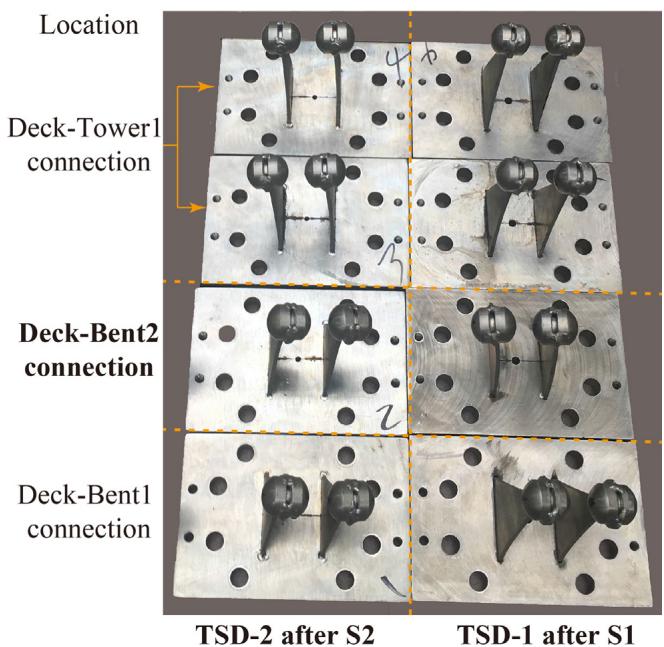
Except for the observed residual deformations, no other physical damage such as fracture or cracks was observed (Fig. 13). Load paths remained uninterrupted, implying that the TSDs reserved their full functions.
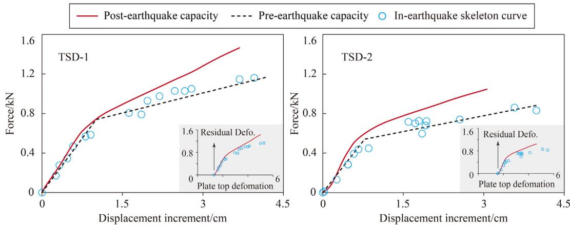
3.3. Post-Earthquake Capacity of TSDs
To assess post-earthquake capacities, monotonic loading tests were performed. As shown in Fig. 14, no strength or stiffness degradation occurs in TSDs despite the multiple ground motions. A slight hardening of post-yield stiffness is observed. Good agreement between pre-earthquake capacity curves and in-earthquake skeleton curves validates the bilinear constitutive models.
4. Assessments on the Low Cycle Fatigue Performance of TSDs
4.1. Assessment Using the Strain-Based Method
4.1.1. Introduction of the Strain-Based Method
The Manson-Coffin model for low cycle fatigue life prediction relates fatigue life (N_f) to the plastic strain range (\Delta\epsilon_p) 19:
where \epsilon_f' is the fatigue ductility coefficient and c is the fatigue ductility exponent. The cumulative damage (D_c) is estimated using Miner's rule 37,38:
4.1.2. Improvements for the Strain-Based Method
To relate strain to the more easily measured displacement (u), the following linear approximation is often used for the elastic state 34:
However, for inelastic deformations, a nonlinear relationship \epsilon(t) = f(u(t)) is required. The plastic strain range within the n-th cycle can be calculated as:
The yield displacement for a triangular plate is:
4.1.3. Assessment Procedures and Results
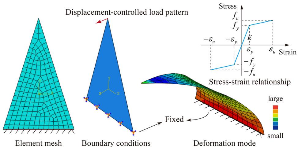
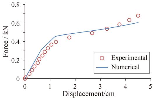
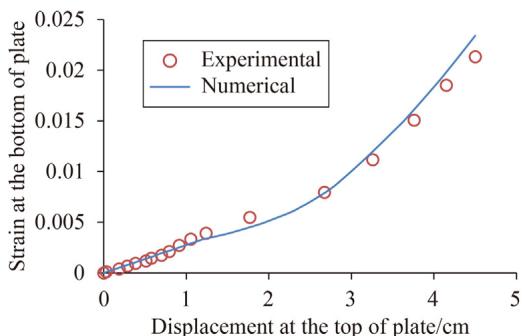
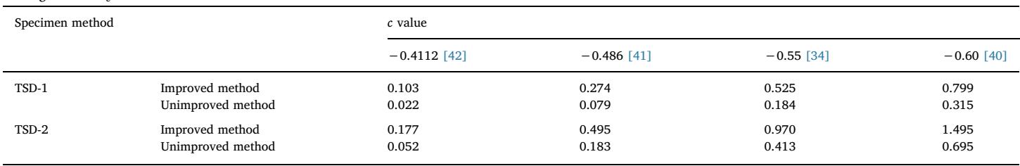
Numerical models in ABAQUS (Fig. 15) were used to establish the strain-displacement relationship. Validated models (Fig. 16, 17) showed that Eq. (3) underestimates strain in the plastic stage (Fig. 18). D_c values for different c values are listed in Table 4. All D_c values are less than unity, indicating no fatigue failure.
4.2. Assessment Using Cumulative Inelastic Deformation
Cumulative Inelastic Deformation (CID) is defined as 46:
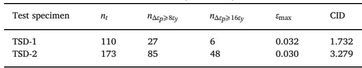
As shown in Table 5, the maximal strain \epsilon_{\max} for both TSDs reached 3\%. CID values of 1.732 (TSD-1) and 3.279 (TSD-2) are far larger than the 0.7 threshold proposed by Usami 47 and the 200\epsilon_y threshold stipulated by AISC 28.
4.3. Assessment Using Equivalent Hysteresis Cycles
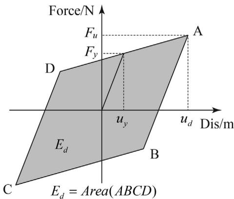
Equivalent hysteretic cycles (EHCs) are calculated based on energy dissipation:
where CED is cumulative energy dissipation and E_d is the energy dissipation at design displacement. The EHCs of TSD-2 are approximately 45 cycles, exceeding the 30 cycles required by Chinese specifications 29.
5. Conclusions
- No fatigue failure occurred in the tested TSDs despite experiencing more than ten seismic excitations.
- Theoretical assessment methods (strain-based, CID, and EHCs) indicate excellent low cycle fatigue performance.
- The improved strain-based damage assessment framework provides a practical tool for metallic hysteretic dampers.
Acknowledgements
This work is supported by the National Basic Research Program of China (No. 2013CB036302) and the National Natural Science Foundation of China (Grant 51778469).
References
Weber F, et al. Guidelines for structural control. 2006. ↩
Guo J, et al. Eng Struct. 2017. ↩
Wei B, et al. J Earthq Eng. 2017. ↩
Wang X, et al. Eng Struct. 2019. ↩
Kasai K, et al. J Struct Eng. 1998. ↩
Vulcano A, et al. Proc 12th WCEE. 2000. ↩
Chen X, et al. J Earthq Tsunami. 2011. ↩
Kelly JM, et al. Bull NZ Soc Earthq Eng. 1972. ↩
Skinner RI, et al. Bull NZ Soc Earthq Eng. 1980. ↩
Whittaker AS, et al. Earthq Spectra. 1991. ↩
Tsai KC, et al. Earthq Spectra. 1993. ↩
Camara A, et al. Struct Eng Int. 2014. ↩
Shen X, et al. Earthq Eng Eng Vib. 2015. ↩
Tanaka K, et al. Hysteretic performance of shear panel dampers. 2000. ↩
Skinner RI, et al. Earthq Eng Struct Dyn. 1974. ↩
Zhou L, et al. Eng Struct. 2019. ↩
Ne D. J Mater. 1972. ↩
Fuchs HO, et al. Metal fatigue in engineering. 1981. ↩
Farfan S. Int J Fatigue. 2004. ↩
Rinaldin G, et al. Soil Dyn Earthq Eng. 2017. ↩
Chen H, et al. J Earthq Eng. 2017. ↩
Kato A, et al. Proc Japan Acad Ser B. 2016. ↩
Uchide T, et al. Earth Planets Sp. 2016. ↩
AISC. Seismic provisions for structural steel buildings. 2010. ↩ ↩
MHURD. Technical specification for seismic energy dissipation of buildings. 2013. ↩ ↩
Tateishi K, et al. Doboku Gakkai Ronbunshuu A. 2008. ↩
Kang L, et al. J Earthq Eng. 2013. ↩
Xu LY, et al. Eng Struct. 2016. ↩
Ancheta TD, et al. NGA-West2 Database. 2012. ↩
Chai YH, et al. Earthq Spectra. 1997.
Miner MA. Am Soc Mech Eng - J Appl Mech. 1945. ↩
Krawinkler H, et al. Comput Struct. 1983. ↩
Borgesson L, ABAQUS. 1996.
Smith RW, et al. NASA Tech Note. 1977.
Mander JB, et al. J Mater Civ Eng. 1994.
Bin W, et al. J Earthq Eng. 1996.
Shi Y, et al. J Constr Steel Res. 2011.
Chen Y, et al. Front Struct Civ Eng. 2014.
Xu L, et al. Int J Plast. 2016.
Wang CL, et al. J Earthq Eng. 2012. ↩
Usami. 10th symp ductile des method bridg. 2007. ↩