(Paragraph Translate)本段译文
# 冲刷作用下砂土中桩群桥梁基础受侧向荷载的桩群效应建模与参数敏感性分析Lianxu Zhou, Ph.D. ^{1} ; Michele Barbato, F.ASCE ^{2} ; and Aijun Ye ^{3}
Abstract: Scour can increase the earthquake-induced damage in pile group foundations. Quantifying the parameter sensitivity of the seismic performance for scoured pile group foundations is essential for the optimal design and retrofit of bridges located in seismic-prone regions. Such quantification requires numerical models that are computationally efficient and accurate in describing the mechanical behavior associated with the complex soil-foundation-structure interaction of these systems. This study proposes an efficient finite-element model (FEM) of pile groups based on a beam on the nonlinear Winkler foundation approach. This FEM uses asymmetric p-multipliers to describe the different soil resistance exerted on leading and trailing piles when applying cyclic lateral loads. The proposed FEM is validated by comparing the numerical response with the experimental measurements taken from a quasi-static test available in the literature and is used to perform an extensive parametric sensitivity analysis to quantify the response sensitivity to 11 structural and soil parameters. Tornado diagrams are employed to identify an importance ranking of these parameters on the seismic performance of scoured pile groups. The obtained results indicate that the proposed FEM is able to capture both the global and local structural responses of pile group foundations. The parametric sensitivity analysis shows that pile group foundations have considerable ductility capacity. Pile diameter and axial load ratio of piles are the most important parameters for the seismic performance of pile groups. Increasing the pile diameter is the most efficient approach to improve the seismic performance of a pile group when considering scour effects. The seismic performance of a scoured pile group deteriorates with increasing piles' axial load ratio. For a deep pile group foundation, seismic performance is very little sensitive to pile length and relative density of sand. Based on the results of the parametric analysis, recommendations are proposed for the seismic design of pile group foundations with scour effects. DOI: 10.1061/JBENF2.BEENG-5861. © 2023 American Society of Civil Engineers.
(Paragraph Translate)本段译文
摘要:冲刷会增加桩群基础在地震作用下产生的损伤。量化冲刷桩群基础抗震性能的参数敏感性对于地震多发地区桥梁的优化设计和改造至关重要。这种量化需要计算高效且能准确描述这些系统复杂土-基础-结构相互作用力学行为的数值模型。本研究提出了一种基于非线性温克尔地基梁方法的桩群高效有限元模型(FEM)。该有限元模型采用非对称$p$-乘数来描述在施加循环侧向荷载时,对前导桩和后随桩施加的不同土体阻力。所提出的有限元模型通过将数值响应与文献中准静态试验的实验测量结果进行比较,验证了其有效性,并用于进行广泛的参数敏感性分析,以量化对11个结构和土体参数的响应敏感性。采用龙卷风图来识别这些参数对冲刷桩群抗震性能的重要性排名。所得结果表明,所提出的有限元模型能够捕捉桩群基础的整体和局部结构响应。参数敏感性分析表明,桩群基础具有相当大的延性能力。桩径和桩的轴向荷载比是影响桩群抗震性能最重要的参数。在考虑冲刷效应时,增加桩径是提高桩群抗震性能最有效的方法。冲刷桩群的抗震性能随桩轴向荷载比的增加而恶化。对于深桩群基础,抗震性能对桩长和砂土相对密度非常不敏感。基于参数分析的结果,提出了考虑冲刷效应的桩群基础抗震设计建议。DOI: 10.1061/JBENF2.BEENG-5861。© 2023 美国土木工程师协会。Author keywords: Bridge scour; Pile group effect; Finite-element model; Parameter sensitivity analysis; Tornado diagram; Ductility capacity; Soil-pile interaction.
(Paragraph Translate)本段译文
作者关键词:桥梁冲刷;桩群效应;有限元模型;参数敏感性分析;龙卷风图;延性能力;土-桩相互作用。Introduction
(Paragraph Translate)本段译文
# 引言Reinforced concrete (RC) pile group foundations are widely used in bridge engineering practice (Fayyazi et al. 2012)24. In addition to bearing vertical loads, pile group foundations can be affected by significant lateral loads produced, e.g., by earthquake ground motions. Existing seismic design specifications often require that the pile group foundations remain in their elastic behavior range under design-level earthquake excitations based on the capacity design philosophy (Mander et al. 1998)37 or allow for the formation of plastic hinges at the pile-cap connection (AASHTO 2022)2. However, pile damage is often unavoidable when strong earthquakes occur (Kawashima et al. 2009)31; (Wei et al. 2008)60. In addition, scour has been reported as the main hazard causing bridge failures (Alipour and Shafei 2016)6; (Capers et al. 2013)19; (Wardhana and Hadipriono 2003)59 by exposing pile group foundations and reducing their lateral load capacity. Recent studies found that scour makes pile group foundations more prone to earthquake-induced damage than columns in a pile-supported bridge system (Wang et al. 2014)58, (Wang et al. 2015)55, (Wang et al. 2019)57. Therefore, the seismic design of scoured pile group foundations is a research topic of significant practical relevance. Extensive experiment- and/or simulation-based studies have focused on soil-pile interaction effects, including pile group effects and inertial/kinematic interaction of soil-pile-structure systems, in which the piles remained in the elastic range or exhibited a limited amount of plastic behavior (Boulanger et al. 1999)14; (Brown et al. 1988)17; (Hussien et al. 2016)27; (Rollins et al. 2005)48. To investigate the seismic failure mechanism and ductility capacity of RC pile group foundations, a few experimental studies adopted cyclic static loads imposed on pile group foundations to simulate earthquake loadings (Banerjee et al. 1987)11; (Chai and Hutchinson 2002)20; (Liu et al. 2020)36; (Park and Falconer 1983)45; (Wang et al. 2016)56; (Zhou et al. 2021a)62.
(Paragraph Translate)本段译文
钢筋混凝土(RC)桩群基础广泛应用于桥梁工程实践中[^24]。除了承受竖向荷载外,桩群基础还会受到例如地震动等产生的显著侧向荷载的影响。现有的抗震设计规范通常要求桩群基础在设计水平地震作用下,基于抗力设计理念保持其弹性行为[^37],或允许在桩帽连接处形成塑性铰[^2]。然而,当强地震发生时,桩的损伤往往是不可避免的[^31];[^60]。此外,冲刷被认为是导致桥梁倒塌的主要危害[^6];[^19];[^59],因为它会暴露桩群基础并降低其侧向承载力。最近的研究发现,冲刷使得桩群基础比桩承式桥梁系统中的桥墩更容易受到地震引起的损伤[^58],[^55],[^57]。因此,冲刷桩群基础的抗震设计是一个具有重要实际意义的研究课题。大量的实验和/或模拟研究都集中在土-桩相互作用效应上,包括桩群效应以及土-桩-结构系统的惯性/运动相互作用,在这些研究中,桩保持在弹性范围内或表现出有限的塑性行为[^14];[^17];[^27];[^48]。为了研究钢筋混凝土桩群基础的地震破坏机制和延性能力,一些实验研究采用了施加在桩群基础上的循环静载荷来模拟地震载荷[^11];[^20];[^36];[^45];[^56];[^62]。Significant research efforts have been devoted to developing numerical approaches for simulating and predicting the behavior of pile group foundations subject to lateral loads. The lateral response of piles is commonly analyzed using the beam on a nonlinear Winkler foundation (BNWF) approach (Adeel et al. 2020)4; (Allotey and El Naggar 2008)7; (Heidari et al. 2014)26; (Liu et al. 2020)36; (Matlock and Ripperger 1956)39; (Wang et al. 1998)54; (Zhang and Hutchinson 2012)61, in which the soil-pile interaction is described using a p-y curve, where p denotes the soil resistance and y denotes the lateral displacement of the pile. Boulanger et al. (1999)14 developed a
(Paragraph Translate)本段译文
大量研究致力于开发数值方法,以模拟和预测承受侧向荷载的桩群基础的行为。桩的侧向响应通常使用非线性温克尔地基梁(BNWF)方法进行分析[^4];[^7];[^26];[^36];[^39];[^54];[^61],其中土-桩相互作用通过$p-y$曲线描述,$p$表示土体阻力,$y$表示桩的侧向位移。Boulanger 等人 (1999)[^14] 开发了一种nonlinear constitutive model based on a combination of three components in series: (1) an elastic spring in parallel with a dashpot to model radiation damping, (2) a plastic spring, and (3) a gap component consisting of a nonlinear closure spring in parallel with a nonlinear drag spring. This material constitutive model was implemented as the uniaxial material denoted PySimpleI in the Open System for Earthquake Engineering Simulation (OpenSees) platform, version 3.3.2 (McKenna 2011)41 and has been widely adopted by both the practicing and academic civil engineering communities (Brandenberg et al. 2007)16; (Hutchinson et al. 2004)29; (Kramer et al. 2008)34. This BNWF-based soil-pile interaction modeling approach has also been validated by a series of centrifuge tests (Boulanger et al. 2003)15, quasi-static tests (Hutchinson et al. 2005)28; (Zhou et al. 2022b)65, and shake table tests (Shang et al. 2018)50. An aspect that has received significant attention for pile group foundations is the quantification and modeling of the so-called pile group effect (Brown et al. 1988)17, which corresponds to the reduction of the lateral capacity of a pile group with respect to the sum of the lateral capacities of the individual piles. This phenomenon is produced by the overlapping of the soil zones affected by the different piles, which is particularly evident for closely spaced pile groups. Due to the pile group effect, different pile rows provide different contributions to the overall lateral capacity of the pile group, with generally higher loads applied to the leading piles, which also tend to exhibit higher curvatures and higher ductility demands (Rollins et al. 2005)48; (Wang et al. 2019)57; (Zhou et al. 2021a)62. Therefore, developing an accurate modeling method for the pile group effect is a critical issue in predicting the performance and the ductile behavior of pile group foundations subject to seismic and lateral cyclic loads. Brown et al. (1988)17 proposed the p-multiplier method to simulate the pile group effect. In this method, the lateral soil resistance of each pile row at a given embedded depth is described using a p-y spring, in which the load p is reduced by a load reduction factor, f_{m} (i.e., the p-multiplier). Different p-multipliers can be used for different pile rows to reproduce the experimentally measured effect of different contributions between leading and trailing piles, providing a simple and widely adopted approach in engineering practice (AASHTO 2020)1. However, for seismically excited pile groups, the loading direction continually changes during the seismic excitation, with piles frequently interchanging their condition between leading and trailing piles multiple times during any given seismic event. To address this issue, previous studies adopted an approximate approach using the average constant value of the p-multiplier for all piles in the group, called group efficiency factor or group reduction factor, to modify the soil resistance in front of the piles (Adeel et al. 2020)4; (Brown et al. 2001)18; (Lemnitzer et al. 2010)35; (Liu et al. 2020)36. This modeling approach has been shown to provide accurate estimates of the global force-displacement response of a pile group (Lemnitzer et al. 2010)35; (Liu et al. 2020)36. However, this uniform reduction factor cannot simulate the difference in lateral soil resistance among different rows in a pile group subjected to cyclic loads, which would be necessary to capture the curvature differences between piles in different rows.
(Paragraph Translate)本段译文
一种基于三个串联组件的非线性本构模型:(1) 与阻尼器并联的弹性弹簧,用于模拟辐射阻尼;(2) 塑性弹簧;(3) 由非线性闭合弹簧与非线性阻力弹簧并联组成的间隙组件。该材料本构模型在地震工程模拟开放系统(OpenSees)平台3.3.2版中作为单轴材料$PySimpleI$实现[^41],并已被土木工程实践和学术界广泛采用[^16];[^29];[^34]。这种基于BNWF的土-桩相互作用建模方法也通过一系列离心机试验[^15]、准静态试验[^28];[^65]和振动台试验[^50]得到了验证。桩群基础一个备受关注的方面是所谓桩群效应的量化和建模[^17],它对应于桩群的侧向承载力相对于单个桩侧向承载力之和的降低。这种现象是由不同桩影响的土体区域重叠产生的,这在密间距桩群中尤为明显。由于桩群效应,不同桩排对桩群整体侧向承载力的贡献不同,通常前排桩承受的荷载更高,并且也倾向于表现出更高的曲率和更高的延性需求[^48];[^57];[^62]。因此,开发一种精确的桩群效应建模方法对于预测桩群基础在地震和侧向循环荷载作用下的性能和延性行为至关重要。Brown 等人 (1988)[^17] 提出了$p$-乘数法来模拟桩群效应。在该方法中,每个桩排在给定埋深处的侧向土体阻力通过$p-y$弹簧描述,其中荷载$p$通过荷载折减系数$f_{m}$(即$p$-乘数)进行折减。不同桩排可以使用不同的$p$-乘数来重现实验测得的前排桩和后排桩之间不同贡献的影响,这在工程实践中是一种简单且被广泛采用的方法[^1]。然而,对于地震作用下的桩群,在地震激励期间荷载方向不断变化,桩在任何给定的地震事件中多次在前排桩和后排桩之间交替其状态。为了解决这个问题,以前的研究采用了一种近似方法,使用桩群中所有桩的$p$-乘数的平均常数值(称为群效率系数或群折减系数)来修改桩前的土体阻力[^4];[^18];[^35];[^36]。这种建模方法已被证明可以提供对桩群整体力-位移响应的准确估计[^35];[^36]。然而,这种均匀折减系数无法模拟在循环荷载作用下桩群中不同桩排之间侧向土体阻力的差异,而这对于捕捉不同桩排之间曲率差异是必要的。In addition, experimental testing can only investigate a limited set of physical and modeling parameter combinations due to the high cost associated with each experimental sample. However, many different parameters can affect the behavior of pile group foundations, particularly when subjected to scour hazards (Blanco et al. 2019)13; (Song et al. 2022)52. To mitigate this issue, a numerical simulation based on finite-element modeling (FEM) can be used to investigate the effects of parameters for which direct experimental testing is unfeasible. Blanco et al. (2019)13 carried out a numerical parametric pushover analysis on the ductile behavior of RC pile group foundations. However, their study was based on a limited number of parameters and, in particular, did not investigate (1) the effects of cyclic loading, (2) different pile group configurations beyond a 2 \times 3 configuration, and (3) the relative importance of different parameters on the seismic performance of the pile group foundations. Therefore, a reliable finite-element modeling approach is a necessary complement to experimental investigations to understand the effects and relative importance of the different parameters that are expected to affect the performance of scoured pile group foundations subject to seismic actions. In addition, an extended parametric sensitivity analysis would significantly help engineers identify the critical parameters for improving the seismic performance of pile foundations with scour potential.
(Paragraph Translate)本段译文
此外,由于每个实验样本的高成本,实验测试只能研究有限的物理和模型参数组合。然而,许多不同的参数会影响桩群基础的行为,特别是在遭受冲刷灾害时[^13];[^52]。为了缓解这个问题,基于有限元建模(FEM)的数值模拟可以用于研究那些直接实验测试不可行的参数的影响。Blanco 等人 (2019)[^13] 对钢筋混凝土桩群基础的延性行为进行了数值参数推覆分析。然而,他们的研究基于有限数量的参数,并且特别没有研究 (1) 循环荷载的影响,(2) 超出 $2 \times 3$ 配置的不同桩群配置,以及 (3) 不同参数对桩群基础抗震性能的相对重要性。因此,可靠的有限元建模方法是实验研究的必要补充,以理解预期影响受地震作用冲刷桩群基础性能的不同参数的影响和相对重要性。此外,扩展的参数敏感性分析将显著帮助工程师识别提高具有冲刷潜力的桩基础抗震性能的关键参数。This paper proposes a practical and straightforward FEM approach, based on a BNWF model with asymmetric p-multipliers, to simulate the soil-pile interaction of pile groups with multiple rows of piles subjected to cyclic loading from seismic excitation. The proposed model is validated by comparing the experimentally measured and numerically simulated global and local response of a scoured RC pile group foundation in sandy soil. This study also performs a detailed parametric sensitivity analysis based on the newly proposed numerical model to identify critical structural and/or soil parameters affecting the seismic performance of scoured pile group foundations and to determine the sensitivity rankings of these parameters.
(Paragraph Translate)本段译文
本文提出了一种基于非对称$p$-乘数BNWF模型的实用且直接的有限元方法,用于模拟多排桩群在地震激励循环荷载作用下的土-桩相互作用。通过比较冲刷砂土中钢筋混凝土桩群基础的实验测量和数值模拟的整体和局部响应,验证了所提出模型的有效性。本研究还基于新提出的数值模型进行了详细的参数敏感性分析,以识别影响冲刷桩群基础抗震性能的关键结构和/或土体参数,并确定这些参数的敏感性排名。Novelty and Relevance
(Paragraph Translate)本段译文
# 新颖性与相关性This paper proposed, for the first time, an asymmetric p-multiplier to better model the differences between leading and trailing piles in RC pile group foundations with multiple pile rows in the direction of the loading and subject to cyclic loading. The proposed approach could be easily extended to other types of piles. This study also performed, for the first time, a comprehensive parametric sensitivity analysis for scoured RC pile group foundations subject to cyclic loading. The sensitivity analysis results were reported in terms of the effects on the piles' performance, particularly in terms of damage levels exhibited by the piles after cyclic loading. The results presented in this paper could represent the basis for future improvements in the design and seismic retrofit of pile group foundations under the combined effects of earthquake loads and scour.
(Paragraph Translate)本段译文
本文首次提出了一种非对称$p$-乘数,以更好地模拟加载方向上具有多排桩的钢筋混凝土桩群基础中前导桩和后随桩之间的差异,并考虑循环荷载作用。所提出的方法可以很容易地扩展到其他类型的桩。本研究还首次对受循环荷载作用的冲刷钢筋混凝土桩群基础进行了全面的参数敏感性分析。敏感性分析结果以对桩性能的影响形式报告,特别是循环荷载后桩所表现出的损伤水平。本文提出的结果可以为未来在地震荷载和冲刷共同作用下桩群基础的设计和抗震加固提供基础。Numerical Modeling and Validation
(Paragraph Translate)本段译文
# 数值建模与验证Description of Experimental Test
(Paragraph Translate)本段译文
# 实验测试描述Zhou et al. (2021a)62 carried out a series of quasi-static tests on RC specimens of scoured 2 \times 3 pile group foundations to investigate their ductile behavior during cyclic loading and their postearthquake vertical load-carrying capacity under different lateral damage states. Their experimental data for Specimen #3 (loaded to a maximum lateral displacement level of 100 \mathrm{~mm}) were used to validate the numerical model in this study. Fig. 1 shows the test layout. The RC pile group consisted of six circular piles with a diameter D = 0.12 \mathrm{~m} and a length H = 4.30 \mathrm{~m}. The pile head was connected together by a concrete cap with a dimension of 1.50 \times 1.00 \times 0.60 \mathrm{~m}. The center-to-center spacing of adjacent piles was 0.36 \mathrm{~m} (i.e., 3D). The specimen was positioned in the center area of a container with an inside dimension of 3.10 (\mathrm{length}) \times 1.50 (\mathrm{width}) \times 4.20 \mathrm{~m} (height) and embedded in homogeneous sand with an average relative density D_{r} = 55\%. The embedded depth was 3.70 \mathrm{~m} (30.83D), and the exposure length of each pile was equal to 0.60 \mathrm{~m}, representing a scour depth of 5D. Table 1 lists the property
(Paragraph Translate)本段译文
Zhou 等人 (2021a)[^62] 对冲刷的 $2 \times 3$ 桩群基础钢筋混凝土试件进行了一系列准静态试验,以研究其在循环荷载作用下的延性行为以及在不同侧向损伤状态下的震后竖向承载力。本研究使用试件 #3(加载至最大侧向位移为 $100 \mathrm{~mm}$)的实验数据来验证数值模型。图1展示了试验布置。钢筋混凝土桩群由六根直径 $D = 0.12 \mathrm{~m}$,长度 $H = 4.30 \mathrm{~m}$ 的圆形桩组成。桩头通过一个尺寸为 $1.50 \times 1.00 \times 0.60 \mathrm{~m}$ 的混凝土桩帽连接。相邻桩的中心距为 $0.36 \mathrm{~m}$(即 $3D$)。试件放置在一个内部尺寸为 $3.10 (\mathrm{长}) \times 1.50 (\mathrm{宽}) \times 4.20 \mathrm{~m}$ (高) 的容器中心区域,并埋入平均相对密度 $D_{r} = 55\%$ 的均质砂土中。埋置深度为 $3.70 \mathrm{~m}$ (30.83D),每根桩的暴露长度为 $0.60 \mathrm{~m}$,代表冲刷深度为 $5D$。表1列出了
Fig. 1. Quasi-static test overview: (a) schematic side view layout; (b) pile steel reinforcement; (c) full view of test; and (d) view of sand and aboveground piles (all units are in cm if not otherwise indicated). (Data from Zhou et al. 2021a.)
(Paragraph Translate)本段译文
图1. 准静态试验概览:(a) 侧视图示意图;(b) 桩钢筋;(c) 试验全貌;(d) 砂土和地上桩视图(除非另有说明,所有单位均为厘米)。(数据来自 Zhou 等人 2021a[^62]。)Table 1. Sand parameters in the experimental test from Zhou et al. (2021a)62
| Parameter | Unit | Value |
|---|---|---|
| Unit weight (\gamma) | kN/m³ | 15.95 |
| Moisture content (w) | % | 0.16 |
| Average relative density (Dr) | % | 55 |
| Friction angle (\varphi) | Degree | 33 |
(Paragraph Translate)本段译文
表1. Zhou 等人 (2021a)[^62] 实验测试中的砂土参数| 参数 | 单位 | 数值 |
|---|---|---|
| 单位重量 (\gamma) | kN/m³ | 15.95 |
| 含水率 (w) | % | 0.16 |
| 平均相对密度 (Dr) | % | 55 |
| 摩擦角 (\varphi) | 度 | 33 |
of the sand used in the test. The total initial axial force applied on the piles was equal to 85.4~\mathrm{kN}, corresponding approximately to an axial load ratio, \eta, equal to 5\% for each pile. The axial load ratio is defined here as follows:
where P = axial (dead) load exerted on the individual pile; f_{c} = peak strength of the unconfined concrete (with f_{c} = 25.20\mathrm{MPa} for this experimental test); and A_{g} = pile gross cross-sectional area (with A_{g} = 0.0113\mathrm{m}^{2} for this experimental test). The lateral load was provided by an actuator, identified as Actuator #1 in Fig. 1(a). Fig. 2 presents the lateral loading protocol for Specimen #3.
(Paragraph Translate)本段译文
试验中使用的砂土的特性。施加在桩上的总初始轴向力等于 $85.4~\mathrm{kN}$,大约对应于每根桩的轴向荷载比 $\eta$ 为 $5\%$。轴向荷载比在此定义如下:其中 P = 施加在单桩上的轴向(静)荷载;f_{c} = 无侧限混凝土的峰值强度(本次实验测试中 f_{c} = 25.20\mathrm{MPa});A_{g} = 桩的总横截面积(本次实验测试中 A_{g} = 0.0113\mathrm{m}^{2})。侧向荷载由一个执行器提供,在图 1(a) 中标识为执行器 #1。图 2 展示了试件 #3 的侧向加载方案。
Fig. 1(b) shows the steel reinforcement configuration for each pile. The longitudinal steel reinforcement ratio was 1.5\% and was provided by six 6-mm-diameter longitudinal steel rebars. The core concrete of the piles was spirally confined by 3.5-mm-diameter galvanized-iron-wires (GIWs) with a center-to-center spacing of 35~\mathrm{mm}, leading to a transverse reinforcement ratio of 1.215\%. Tables 2 and 3 summarize the mechanical parameters of the concrete and steel used in the pile group specimen.
(Paragraph Translate)本段译文
图1(b) 显示了每根桩的钢筋配置。纵向钢筋配筋率为 $1.5\%$,由六根直径为6毫米的纵向钢筋提供。桩的混凝土核心通过直径为3.5毫米的镀锌铁丝(GIW)以35毫米的中心距螺旋约束,横向配筋率为 $1.215\%$。表2和表3总结了桩群试件中使用的混凝土和钢材的力学参数。
Fig. 2. Loading protocol for Specimen #3 according to Zhou et al. (2021a)62.
(Paragraph Translate)本段译文
图2. 根据 Zhou 等人 (2021a)[^62] 的试件 #3 加载方案。Selection of p-Multipliers for Pile Group Effect
(Paragraph Translate)本段译文
# 桩群效应 $p$-乘数的选择The p-multipliers have been typically obtained from full- or small-scale experimental quasi-static or centrifuge tests, or estimated using finite-element analysis, often based on three-dimensional (3D) models. Table 4 summarizes the values of the p-multipliers for pile groups in sandy soil reported in the literature. It is observed that the value of the p-multiplier mainly depends on pile layout, pile-row location, and the ratio of pile spacing to diameter, as reported in previous studies (AASHTO 2020)1; (Adeel et al. 2020)4, whereas the relative density of sand seems to have a relatively small effect. The value of f_{m} increases with the increase of pile center-to-center spacing S, and the p-multiplier for leading piles is generally larger than that for trailing piles. Based on the collected data of f_{m} listed in Table 4, the mean values of f_{m} for first-, second-, and third-row piles of a three-row pile group with S = 3D are 0.75, 0.41, and 0.33 and their standard deviations are 0.058, 0.034, and 0.055, respectively. For a two-row pile group with S = 3D, the mean values of the p-multiplier for the first- and second-row piles are 0.84 and 0.56, and their standard deviations are 0.048 and 0.082, respectively.
(Paragraph Translate)本段译文
$p$-乘数通常通过全尺寸或小尺寸实验准静态或离心机试验获得,或使用有限元分析估算,通常基于三维(3D)模型。表4总结了文献中报道的砂土桩群$p$-乘数值。据观察,$p$-乘数的值主要取决于桩的布置、桩排位置以及桩间距与直径之比,如先前研究所示[^1];[^4],而砂土的相对密度似乎影响相对较小。$f_{m}$ 的值随桩中心距 $S$ 的增加而增加,且前排桩的$p$-乘数通常大于后排桩。根据表4中列出的$f_{m}$收集数据,对于 $S = 3D$ 的三排桩群,第一排、第二排和第三排桩的$f_{m}$平均值分别为0.75、0.41和0.33,其标准差分别为0.058、0.034和0.055。对于 $S = 3D$ 的两排桩群,第一排和第二排桩的$p$-乘数平均值分别为0.84和0.56,其标准差分别为0.048和0.082。Fig. 3 compares the p-multipliers for three-row pile groups obtained from the literature and reported in Table 4 with the values recommended by the AASHTO specifications as a function of the ratio S/D (AASHTO 2020)1. The values suggested by AASHTO refer to pile groups with three or more rows in the load direction; they are equal to 0.8, 0.4, and 0.3 for the first, second, and third or higher row when S = 3D and equal to 1.0, 0.85, and 0.7 when S = 5D, respectively. A linear interpolation (shown in Fig. 3) was used to determine the p-multiplier for pile spacing contained between 3D and 5D. These values were found to be generally in good agreement with the p-multipliers obtained from the literature;
(Paragraph Translate)本段译文
图3比较了文献中获得并列于表4的三排桩群的$p$-乘数,与AASHTO规范推荐的$S/D$比值的函数值[^1]。AASHTO建议的值适用于加载方向上三排或更多排的桩群;当 $S = 3D$ 时,第一排、第二排和第三排或更高排的$p$-乘数分别为0.8、0.4和0.3,当 $S = 5D$ 时,则分别为1.0、0.85和0.7。采用线性插值(如图3所示)来确定桩间距介于 $3D$ 和 $5D$ 之间的$p$-乘数。发现这些值与文献中获得的$p$-乘数基本一致;Table 2. Mechanical properties of concrete from Zhou et al. (2021a)62
| Material | Peak strength (MPa) | Strain corresponding to peak strength | Strength at ultimate strain (MPa) | Ultimate strain |
|---|---|---|---|---|
| Unconfined concrete | 25.20 | 0.0020 | 5.04 | 0.006 |
| Confined concrete | 29.05 | 0.0037 | 5.82 | 0.021 |
(Paragraph Translate)本段译文
表2. Zhou 等人 (2021a)[^62] 混凝土力学性能| 材料 | 峰值强度 (MPa) | 峰值强度对应的应变 | 极限应变强度 (MPa) | 极限应变 |
|---|---|---|---|---|
| 无侧限混凝土 | 25.20 | 0.0020 | 5.04 | 0.006 |
| 约束混凝土 | 29.05 | 0.0037 | 5.82 | 0.021 |
Table 3. Mechanical properties of steel reinforcement from Zhou et al. (2021a)62
| Material | Elastic modulus (MPa) | Yield strength (MPa) | Peak strength (MPa) | Strain corresponding to peak strength |
|---|---|---|---|---|
| \varphi6 mm rebars | 216,553 | 429 | 670 | 0.120 |
| \varphi3.5 mm GIW | 135,441 | 317 | 421 | 0.148 |
(Paragraph Translate)本段译文
表3. Zhou 等人 (2021a)[^62] 钢筋力学性能| 材料 | 弹性模量 (MPa) | 屈服强度 (MPa) | 峰值强度 (MPa) | 峰值强度对应的应变 |
|---|---|---|---|---|
| \varphi6 毫米钢筋 | 216,553 | 429 | 670 | 0.120 |
| \varphi3.5 毫米镀锌铁丝 | 135,441 | 317 | 421 | 0.148 |
thus, they were used in the modeling performed in this study to estimate the p-multipliers. For the three-row pile groups with S = 2.5D, the p-multipliers were taken equal to the mean values obtained from Table 4, i.e., f_{m} = 0.66, 0.38, and 0.29 for the first, second, and third row of piles, respectively. For the two-row pile groups with a pile spacing S = 3D, the p-multipliers were taken equal to the mean values obtained from Table 4, i.e., f_{m} = 0.84 and 0.56 for the first and second row of piles, respectively.
(Paragraph Translate)本段译文
因此,它们被用于本研究中的建模,以估计 $p$-乘数。对于 $S = 2.5D$ 的三排桩群,其 $p$-乘数取自表4的平均值,即第一排、第二排和第三排桩分别为 $f_{m} = 0.66$、0.38和0.29。对于桩间距 $S = 3D$ 的两排桩群,其 $p$-乘数取自表4的平均值,即第一排和第二排桩分别为 $f_{m} = 0.84$和0.56。Finite-Element Modeling
(Paragraph Translate)本段译文
# 有限元建模A finite-element (FE) model of the pile group foundation in sandy soil was built based on the BNWF approach to simulate the quasi-static test previously described. Fig. 4 illustrates the FE numerical model, which is developed and analyzed using the OpenSees software framework (McKenna 2011)41.
(Paragraph Translate)本段译文
基于BNWF方法,建立了砂土中桩群基础的有限元(FE)模型,以模拟前面描述的准静态试验。图4展示了有限元数值模型,该模型是使用OpenSees软件框架[^41]开发和分析的。Modeling of Piles and Cap
(Paragraph Translate)本段译文
# 桩和承台建模The piles were modeled using displacement-based beam-column elements with distributed plasticity and fiber sections (Barbato et al. 2010)12; (Liu et al. 2020)36. An FE mesh convergence analysis was performed in this study to determine an appropriate FE discretization for the piles. This analysis indicated that the FEMs with pile element lengths equal to 0.5D, 1.0D, and 1.25D produce a converged (i.e., almost identical) response for both global and local response quantities. Therefore, each pile was discretized into FEs of length equal to 0.12\mathrm{m} (i.e., 1D), except for the pile bottom element with a length of 0.22\mathrm{m}, as shown in Fig. 4(a). Each beam-column FE has five Gauss-Lobatto integration points. Different constitutive models were assigned to fibers corresponding to unconfined concrete, confined concrete, and longitudinal steel reinforcement. In particular, the axial stress-strain behavior of the concrete fibers was simulated using the uniaxial material Concrete01, which corresponds to the Kent-Scott-Park model with zero strength in tension (Scott et al. 1982)49. This model has been shown to properly represent the stress-strain behavior of GIW-confined concrete (Zhou et al. 2021b)64, (Zhou et al. 2022b)65. Fig. 4(c) shows the backbone curves of this concrete model. The model parameters for confined and unconfined concrete are listed in Table 2. The axial stress-strain behavior of the longitudinal steel reinforcement fibers was modeled using the uniaxial material Steel02, which corresponds to the Menegotto-Pinto model with kinematic and isotropic strain hardening (Filippou et al. 1983)25. The model parameters for the longitudinal steel reinforcement are given in Table 3. The pile cap was modeled using two elastic beam-column elements, and the cap bottom was connected with all six pile heads by elastic beam-column elements. The axial and flexure stiffnesses of these elastic elements were set equal to 1,000 times those of the pile elements to simulate an approximatively rigid link between the cap and the pile heads. The gravity load corresponding to the self-weight of each pile element was applied to the corresponding nodes, and the cap weight was applied to the cap center. A constant vertical load was imposed on the cap-top node to produce an axial load ratio of 5\% on each pile head section. All the degrees of freedom (DOFs) of the aboveground nodes were left unconstrained. For the belowground nodes, because the lateral loads were applied to the cap-center along the three-row pile direction only (i.e., along the global X-axis), the two translational DOFs in the XY plane were connected to zero-length elements representing the soil-pile interaction (which is described in the following section), the rotational DOF about the Z-axis was a free DOF, and the other three remaining DOFs (i.e., translation along the Z-axis and rotations about the X- and Y-axis) were fixed.
(Paragraph Translate)本段译文
桩采用基于位移的梁柱单元,具有分布塑性和纤维截面模型[^12];[^36]。本研究进行了有限元网格收敛性分析,以确定桩的适当有限元离散化。该分析表明,桩单元长度分别为 $0.5D$、$1.0D$ 和 $1.25D$ 的有限元模型,在整体和局部响应量方面均产生了收敛(即几乎相同)的响应。因此,每根桩被离散为长度为 $0.12\mathrm{m}$(即 $1D$)的有限元,除了桩底单元长度为 $0.22\mathrm{m}$,如图4(a)所示。每个梁柱有限元具有五个高斯-洛巴托积分点。不同的本构模型被分配给对应于无侧限混凝土、约束混凝土和纵向钢筋的纤维。特别是,混凝土纤维的轴向应力-应变行为采用单轴材料Concrete01模拟,该材料对应于Kent-Scott-Park模型,具有零抗拉强度[^49]。该模型已被证明能很好地表示镀锌铁丝约束混凝土的应力-应变行为[^64],[^65]。图4(c)显示了该混凝土模型的骨架曲线。约束和无侧限混凝土的模型参数列于表2。纵向钢筋纤维的轴向应力-应变行为采用单轴材料Steel02模拟,该材料对应于Menegotto-Pinto模型,具有运动和各向同性应变硬化[^25]。纵向钢筋的模型参数列于表3。桩帽采用两个弹性梁柱单元建模,桩帽底部通过弹性梁柱单元与所有六个桩头连接。这些弹性单元的轴向和弯曲刚度设置为桩单元的1000倍,以模拟桩帽与桩头之间的近似刚性连接。对应于每个桩单元自重的重力荷载施加到相应的节点,桩帽重量施加到桩帽中心。在桩帽顶部节点施加一个恒定的竖向荷载,使每个桩头截面的轴向荷载比为 $5\%$。地上所有节点的自由度(DOFs)保持不受约束。对于地下节点,由于侧向荷载仅沿三排桩方向(即沿全局$X$轴)施加到桩帽中心,因此 $XY$ 平面中的两个平移自由度连接到表示土-桩相互作用的零长度单元(在下一节中描述),绕 $Z$ 轴的旋转自由度是自由自由度,其余三个自由度(即沿 $Z$ 轴的平移以及绕 $X$ 轴和 $Y$ 轴的旋转)被固定。Modeling of Soil-Pile Interaction Considering the Pile Group Effect
(Paragraph Translate)本段译文
# 考虑桩群效应的土-桩相互作用建模This study introduced an innovative approach to model the pile group effect in soil-pile interaction systems subject to cyclic or dynamic loads. In fact, the approach commonly adopted in the literature describes the soil resistance to the lateral movement of a pile group through the use of a constant p-multiplier (i.e., the so-called group efficiency factor) equally applied to all piles of the group (Adeel et al. 2020)4; (Brown et al. 2001)18; (Lemnitzer et al. 2010)35; (Liu et al. 2020)36. This group efficiency factor is commonly calculated as the average value of the p-multipliers for different pile rows and is adopted because different piles alternate the roles of leading and trailing piles during cyclic loading or earthquake excitations. However, this constant reduction factor cannot correctly simulate the difference in lateral soil resistance among different rows in a pile group under cyclic loading, leading to inaccurate estimates of differential curvatures for piles in different rows.
(Paragraph Translate)本段译文
本研究引入了一种创新的方法来模拟土-桩相互作用系统中受循环或动态荷载作用的桩群效应。事实上,文献中普遍采用的方法是通过使用一个常数 $p$-乘数(即所谓的群效率因子)来描述桩群横向移动的土体阻力,并将其均匀应用于桩群中的所有桩[^4];[^18];[^35];[^36]。这个群效率因子通常计算为不同桩排 $p$-乘数的平均值,并被采用,因为在循环荷载或地震激励期间,不同的桩会在前排桩和后排桩的角色之间交替。然而,这种恒定的折减系数不能正确模拟循环荷载作用下桩群中不同桩排之间侧向土体阻力的差异,导致对不同桩排桩的差异曲率估计不准确。This study proposed a new practical modeling method, which simulates the soil resistance in front of a pile at depth h by using two parallel springs consisting of (1) a common nonlinear p-y spring and (2) a nonlinear asymmetric spring, as illustrated in Fig. 4(e). In particular, the end nodes of each pile element below the ground surface were connected to the fixed nodes representing the soil site via zero-length elements. The load-displacement response of the zero-length element was described by a nonlinear p-y spring and a nonlinear asymmetric spring in parallel in the horizontal direction (X-axis) and by a nonlinear t-z spring in the vertical direction (Y-axis). The nonlinear p-y spring was modeled using the uniaxial material PySimple1 in OpenSees (Boulanger et al. 1999)14, which is commonly used to describe the force-displacement relation for soils acting on piles. The backbone of the p-y constitutive model for sand is given as follows (API 2007)8; (Chai and Song 2012)21:
(Paragraph Translate)本段译文
本研究提出了一种新的实用建模方法,该方法通过使用两个并联弹簧来模拟桩在深度 $h$ 处的土体阻力,这两个弹簧包括 (1) 一个常见的非线性 $p-y$ 弹簧和 (2) 一个非线性非对称弹簧,如图4(e)所示。具体而言,地面以下每个桩单元的端节点通过零长度单元连接到代表土体场地的固定节点。零长度单元的荷载-位移响应由水平方向($X$轴)上并联的非线性 $p-y$ 弹簧和非线性非对称弹簧描述,以及竖直方向($Y$轴)上的非线性 $t-z$ 弹簧描述。非线性 $p-y$ 弹簧使用OpenSees中的单轴材料PySimple1进行建模[^14],该材料常用于描述作用在桩上的土体受力与位移关系。砂土的 $p-y$ 本构模型的骨架曲线如下所示[^8];[^21]:Table 4. Values available in the literature of p-multipliers for pile groups with three or two rows in the load direction
| Pile rows | References (year) | Soil properties | Method used to estimate p-multipliers | Pile layout | D (m) | S/D | 1st row | 2nd row | 3rd row | |
|---|---|---|---|---|---|---|---|---|---|---|
| 3 | Brown et al. (1988)17 | Saturated medium dense sand (D_r=50\%) over stiff clay | Full-scale test | 3×3 | 0.273 | 3 | 0.8 | 0.4 | 0.3 | |
| Rollins et al. (2005)48 | Sand to silty sand (D_r\approx 50\%) | Full-scale test | 3×3 | 0.324 | 3.29 | 0.8 | 0.4 | 0.4 | ||
| Christensen (2006)22 | Medium to dense sand (\varphi=35\sim 40^\circ) over soft clay and silt | Numerical fitting | NS | NS | 2.5 | 0.75 | 0.34 | 0.34 | ||
| McVay et al. (1995)42 | Medium loose sand (D_r=33\%) | Full-scale test | 3×3 | 0.324 | 5.65 | 1 | 0.7 | 0.65 | ||
| Medium dense sand (D_r=55\%) | 1/45 scale centrifuge test | 3×3 | 0.0095 | 3 | 0.65 | 0.45 | 0.35 | |||
| Medium loose sand (D_r=33\%) | Medium dense sand (D_r=55\%) | 3×3 | 0.0095 | 3 | 0.8 | 0.45 | 0.3 | |||
| Medium dense sand (D_r=55\%) | Medium loose sand (D_r=36\%) and medium dense sand (D_r=55\%) | 1/45 scale centrifuge test | 3×3 | 0.0095 | 3 | 0.8 | 0.4 | 0.3 | ||
| Kotthuas (1992)33 | Dense sand (D_r=97\%) | NS | 1×3 | - | 3 | 0.75 | 0.42 | 0.45 | ||
| NS | 1×3 | - | 4 | 0.95 | 0.6 | 0.65 | ||||
| Kim and Yoon (2011)32 | Dense sand (D_r=73\%) | Small-scale tests | 1×3 | 0.012 | 4 | 0.85 | 0.6 | 0.45 | ||
| Medium dense sand (D_r=55\%) | Small-scale tests | 3×3 | 0.012 | 3 | 0.7 | 0.35 | 0.3 | |||
| Vakili et al. (2021)53 | Loose sand (D_r=39.5\%) | Small-scale tests | 1×3 | 0.02 | 2.5 | 0.7 | 0.44 | 0.29 | ||
| Loose sand (D_r=39.5\%) | Small-scale tests | 2×3 | 0.02 | 2.5 | 0.54 | 0.36 | 0.25 | |||
| 2 | Reese et al. (2006)46 | NS | NS | 2×2 | NS | 3 | 0.85 | 0.61 | - | |
| NS | 2×2 | NS | 5 | 0.92 | 0.77 | - | ||||
| NS | 1×2 | NS | 3 | 0.93 | 0.72 | - | ||||
| Albusoda et al. (2018)5 | Loose sand (D_r=32\%) over two dense sand layers (D_r=50\% and 70\%) | Small-scale tests | 2×2 | 0.01 | 3 | 0.79 | 0.51 | - | ||
| 3DFEM | 2×2 | 0.01 | 6 | 0.88 | 0.72 | - | ||||
| 3DFEM | 2×2 | 0.01 | 3 | 0.81 | 0.5 | - | ||||
| 3DFEM | 2×2 | 0.01 | 6 | 0.83 | 0.69 | - | ||||
| Vakili et al. (2021)53 | Loose sand (D_r=39.5\%) | Small-scale tests | 1×2 | 0.02 | 2.5 | 0.6 | 0.51 | - | ||
| Small-scale tests | 1×2 | 0.02 | 3.5 | 0.88 | 0.61 | - | ||||
| Abbas et al. (2016)3 | Medium over loose and dense sand | 3DFEM | 2×2 | 0.91 | 3 | 0.83 | 0.54 | - |
Note: \mathrm{NS} = not specified; and - = not present.
(Paragraph Translate)本段译文
表4. 文献中已有的加载方向上三排或两排桩群的 $p$-乘数值| 桩排数 | 参考文献 (年份) | 土体特性 | p-乘数估计方法 | 桩布置 | D (m) | S/D | 第一排 | 第二排 | 第三排 | |
|---|---|---|---|---|---|---|---|---|---|---|
| 3 | Brown 等人 (1988)17 | 饱和中密砂 (D_r=50\%) 覆盖硬粘土 | 足尺试验 | 3×3 | 0.273 | 3 | 0.8 | 0.4 | 0.3 | |
| Rollins 等人 (2005)48 | 砂土至粉砂土 (D_r\approx 50\%) | 足尺试验 | 3×3 | 0.324 | 3.29 | 0.8 | 0.4 | 0.4 | ||
| Christensen (2006)22 | 中密至密实砂 (\varphi=35\sim 40^\circ) 覆盖软粘土和粉土 | 数值拟合 | 未指定 | 未指定 | 2.5 | 0.75 | 0.34 | 0.34 | ||
| McVay 等人 (1995)42 | 中松砂 (D_r=33\%) | 足尺试验 | 3×3 | 0.324 | 5.65 | 1 | 0.7 | 0.65 | ||
| 中密砂 (D_r=55\%) | 1/45 比例离心机试验 | 3×3 | 0.0095 | 3 | 0.65 | 0.45 | 0.35 | |||
| 中松砂 (D_r=33\%) | 中密砂 (D_r=55\%) | 3×3 | 0.0095 | 3 | 0.8 | 0.45 | 0.3 | |||
| 中密砂 (D_r=55\%) | 中松砂 (D_r=36\%) 和中密砂 (D_r=55\%) | 1/45 比例离心机试验 | 3×3 | 0.0095 | 3 | 0.8 | 0.4 | 0.3 | ||
| Kotthuas (1992)33 | 密实砂 (D_r=97\%) | 未指定 | 1×3 | - | 3 | 0.75 | 0.42 | 0.45 | ||
| 未指定 | 1×3 | - | 4 | 0.95 | 0.6 | 0.65 | ||||
| Kim and Yoon (2011)32 | 密实砂 (D_r=73\%) | 小尺寸试验 | 1×3 | 0.012 | 4 | 0.85 | 0.6 | 0.45 | ||
| 中密砂 (D_r=55\%) | 小尺寸试验 | 3×3 | 0.012 | 3 | 0.7 | 0.35 | 0.3 | |||
| Vakili 等人 (2021)53 | 松砂 (D_r=39.5\%) | 小尺寸试验 | 1×3 | 0.02 | 2.5 | 0.7 | 0.44 | 0.29 | ||
| 松砂 (D_r=39.5\%) | 小尺寸试验 | 2×3 | 0.02 | 2.5 | 0.54 | 0.36 | 0.25 | |||
| 2 | Reese 等人 (2006)46 | 未指定 | 未指定 | 2×2 | 未指定 | 3 | 0.85 | 0.61 | - | |
| 未指定 | 2×2 | 未指定 | 5 | 0.92 | 0.77 | - | ||||
| 未指定 | 1×2 | 未指定 | 3 | 0.93 | 0.72 | - | ||||
| Albusoda 等人 (2018)5 | 松砂 (D_r=32\%) 覆盖两层密实砂 (D_r=50\% 和 70\%) | 小尺寸试验 | 2×2 | 0.01 | 3 | 0.79 | 0.51 | - | ||
| 3D有限元 | 2×2 | 0.01 | 6 | 0.88 | 0.72 | - | ||||
| 3D有限元 | 2×2 | 0.01 | 3 | 0.81 | 0.5 | - | ||||
| 3D有限元 | 2×2 | 0.01 | 6 | 0.83 | 0.69 | - | ||||
| Vakili 等人 (2021)53 | 松砂 (D_r=39.5\%) | 小尺寸试验 | 1×2 | 0.02 | 2.5 | 0.6 | 0.51 | - | ||
| 小尺寸试验 | 1×2 | 0.02 | 3.5 | 0.88 | 0.61 | - | ||||
| Abbas 等人 (2016)3 | 中等覆盖松散和密实砂 | 3D有限元 | 2×2 | 0.91 | 3 | 0.83 | 0.54 | - |
注:\mathrm{NS} = 未指定;- = 不存在。
where p = lateral resistance of soil at the embedded depth h; y = lateral deflection of the pile at depth h; p_u = ultimate resistance of the sand at depth h; A = loading factor, which is equal to 0.9 for cyclic loading; p_{us} and p_{ud} = ultimate resistances of soil in the shallow and deep regions, respectively; n_h = initial subgrade reaction modulus of sand, which can be obtained from API specification as a function of the sand friction angle; \gamma = soil weight density; and C_1, C_2, and C_3 = nondimensional coefficients that depend on the effective friction angle (API 2007)8; (Chai and Song 2012)21.
(Paragraph Translate)本段译文
其中 $p =$ 埋深 $h$ 处土体的侧向阻力;$y =$ 埋深 $h$ 处桩的侧向位移;$p_u =$ 埋深 $h$ 处砂土的极限阻力;$A =$ 荷载系数,对于循环荷载等于0.9;$p_{us}$ 和 $p_{ud} =$ 分别为浅层和深层土体的极限阻力;$n_h =$ 砂土的初始地基反力模量,可根据API规范作为砂土内摩擦角的函数获得;$\gamma =$ 土体容重;$C_1$、$C_2$ 和 $C_3 =$ 无量纲系数,取决于有效内摩擦角[^8];[^21]。
Fig. 3. p-Multipliers for three-row pile groups in the sand.
(Paragraph Translate)本段译文
图3. 砂土中三排桩群的 $p$-乘数。The nonlinear asymmetric spring is approximatively modeled using the uniaxial material QzSimple1 in OpenSees (Boulanger et al. 1999)14, which has a behavior similar to the constitutive model for the p-y spring on the compression side but has an asymmetric and smaller soil strength on the tension side, as shown in Fig. 4(g). The parameters of the backbone q-z curve are adjusted to approximately reproduce the same backbone curve used for the p-y spring, whereas the suction factor is set equal to zero. This nonlinear asymmetric spring is used to model the asymmetric value of the p-multiplier of any given pile when a pile group is subject to cyclic or seismic loads, i.e., when two different p-multiplier values need to be applied to the same pile in a given row that is switching from leading (corresponding to the larger p-multiplier value, f_{m,t}) to trailing pile (corresponding to the smaller p-multiplier value, f_{m,t}) as the load changes direction. The asymmetric spring is oriented so that the compression side coincides with the side in which the pile is nontrailing. It is noted here that a single asymmetric p-y spring (with two different p-multipliers for the leading and trailing directions) could be used to produce the same behavior obtained through the combination of the symmetric p-y spring and the
(Paragraph Translate)本段译文
非线性非对称弹簧使用OpenSees中的单轴材料QzSimple1近似建模[^14],其行为类似于 $p-y$ 弹簧在受压侧的本构模型,但在受拉侧具有非对称且较小的土体强度,如图4(g)所示。骨架 $q-z$ 曲线的参数经过调整,以近似重现用于 $p-y$ 弹簧的相同骨架曲线,而吸力系数设置为零。这种非线性非对称弹簧用于模拟在桩群受到循环或地震荷载时,任何给定桩的 $p$-乘数的非对称值,即当荷载方向改变时,同一排中的同一桩从前导桩(对应较大的 $p$-乘数值,$f_{m,t}$)切换到后随桩(对应较小的 $p$-乘数值,$f_{m,t}$)时,需要施加两个不同的 $p$-乘数值。非对称弹簧的朝向使得受压侧与桩处于非后随状态的一侧重合。在此需要注意的是,一个单一的非对称 $p-y$ 弹簧(在前导和后随方向上具有两个不同的 $p$-乘数)可以用于产生通过对称 $p-y$ 弹簧和
Fig. 4. Numerical modeling: (a) schematic illustration of the entire model; (b) fiber section discretization of the piles; (c) concrete model; (d) steel model; (e) soil-pile interaction modeling; (f) p-y spring model; (g) asymmetric spring model; and (h) ENT spring model.
(Paragraph Translate)本段译文
图4. 数值建模:(a) 整个模型的示意图;(b) 桩的纤维截面离散化;(c) 混凝土模型;(d) 钢材模型;(e) 土-桩相互作用建模;(f) $p-y$ 弹簧模型;(g) 非对称弹簧模型;(h) ENT 弹簧模型。asymmetric q-z spring proposed in this study. However, such a constitutive model is not currently available in OpenSees. Thus, the soil resistances of the two lateral parallel springs are given as follows:
where p_{sym}^{(n)} = \mathrm{soil} resistance for the nth row piles provided by the symmetric p-y spring; p_{asym}^{(n)} = \mathrm{soil} resistance for the nth row piles provided by the asymmetric spring; superscript n = 1,2,\ldots ,n_{\mathrm{max}} = pile row number; and n_{\mathrm{max}} = total number of rows. As a result, the required input parameters of the PySimple1 material in OpenSees, p_{\mathrm{ult}} and y_{50} (Blanco et al. 2019)13, are given by
where p_{\mathrm{ult}} = ultimate soil resistance provided by the symmetric p-y spring; y_{50} = soil displacement at 50\% of p_{\mathrm{ult}} and L_{t} = tributary length of the soil-pile contact associated with the given node. The required input parameters of the QzSimple1 material, q_{\mathrm{ult}} and z_{50} are given by
where q_{\mathrm{ult}} = ultimate soil resistance provided by the asymmetric q-z spring; and z_{50} = soil displacement at 50\% of q_{\mathrm{ult}}. It is noted here that, for cases in which the p-multiplier value for a pile row remains constant in the two opposite loading directions, the soil resistance corresponding to this pile row can be modeled more simply by using only the symmetric p-y springs with the appropriate value of the p-multiplier. For the numerical model of the quasi-static test considered in this study, which involves a pile group foundation with three rows of piles in the loading direction with a 3D pile spacing, the p-multiplier values are f_{m,l}^{(1)} = f_{m,t}^{(1)} = 0.8, f_{m,t}^{(1)} = f_{m,t}^{(3)} = 0.3, and f_{m}^{(2)} = f_{m,l}^{(2)} = f_{m,t}^{(2)} = 0.4.
(Paragraph Translate)本段译文
本研究提出的非对称 $q-z$ 弹簧。然而,OpenSees 中目前没有这样的本构模型。因此,两个侧向并联弹簧的土体阻力如下所示:其中 p_{sym}^{(n)} = 对称 p-y 弹簧为第 n 排桩提供的土体阻力;p_{asym}^{(n)} = 非对称弹簧为第 n 排桩提供的土体阻力;上标 n = 1,2,\ldots ,n_{\mathrm{max}} = 桩排号;n_{\mathrm{max}} = 总排数。因此,OpenSees 中 PySimple1 材料所需的输入参数 p_{\mathrm{ult}} 和 y_{50} (Blanco 等人 2019)13 由下式给出:
其中 p_{\mathrm{ult}} = 对称 p-y 弹簧提供的极限土体阻力;y_{50} = 土体位移达到 p_{\mathrm{ult}} 的 50\% 时的位移;L_{t} = 与给定节点相关的土 - 桩接触的有效长度。QzSimple1 材料所需的输入参数 q_{\mathrm{ult}} 和 z_{50} 由下式给出:
其中 q_{\mathrm{ult}} = 非对称 q-z 弹簧提供的极限土体阻力;z_{50} = 土体位移达到 q_{\mathrm{ult}} 的 50\% 时的位移。在此需要指出的是,对于桩排在两个相反加载方向上的 p- 乘数值保持不变的情况,可以通过仅使用具有适当 p- 乘数值的对称 p-y 弹簧更简单地模拟该桩排对应的土体阻力。对于本研究中考虑的准静态试验数值模型,该模型涉及加载方向上三排桩且桩间距为 3D 的桩群基础,其 p- 乘数值为 f_{m,l}^{(1)} = f_{m,t}^{(1)} = 0.8,f_{m,t}^{(1)} = f_{m,t}^{(3)} = 0.3,以及 f_{m}^{(2)} = f_{m,l}^{(2)} = f_{m,t}^{(2)} = 0.4。
The vertical soil-pile friction behavior was simulated using a t-z spring modeled with the TzSimple1 material in OpenSees (Boulanger et al. 1999)14. The corresponding input parameters t_{\mathrm{ult}} and z_{50} are given by (Mosher 1984)44
where t_{\mathrm{ult}} = ultimate friction force at the soil-pile interface within the tributary length L_{t}, k_{0} = coefficient of lateral earth pressure at rest and is set equal to 0.4; \phi = friction angle of sand; z_{50} = displacement at which the friction force reaches 50\% of t_{\mathrm{ult}} and k = initial tangent stiffness and can be expressed as a function of the friction angle (Mosher 1984)44. Finally, the FE model of the benchmark example used for validation describes the boundary conditions at the pile tips with vertical springs, the behavior of which is given by an elastic-no-tension (ENT) material with an initial stiffness of 1\times 10^{7}\mathrm{kN / m} as shown in Fig. 4(h). The modeling parameter values for the quasi-static test used in Eqs. (2)-(13) are given in Table 5.
(Paragraph Translate)本段译文
竖向土-桩摩擦行为使用OpenSees中的$TzSimple1$材料模拟,该材料通过 $t-z$ 弹簧进行建模[^14]。相应的输入参数 $t_{\mathrm{ult}}$ 和 $z_{50}$ 由以下公式给出[^44]:其中 t_{\mathrm{ult}} = 在有效长度 L_{t} 内土 - 桩界面处的极限摩擦力,k_{0} = 静止土压力系数,设为 0.4;\phi = 砂土的摩擦角;z_{50} = 摩擦力达到 t_{\mathrm{ult}} 的 50\% 时的位移,k = 初始切线刚度,可表示为摩擦角的函数44。最后,用于验证的基准示例有限元模型描述了桩尖处的边界条件,采用竖向弹簧,其行为由初始刚度为 1\times 10^{7}\mathrm{kN / m} 的弹性 - 无拉力(ENT)材料给出,如图 4(h)所示。式 (2)-(13) 中准静态试验的建模参数值列于表 5。
Table 5. Modeling parameters for the sand soil in the benchmark example
| Parameter | Unit | Value |
|---|---|---|
| C1 | None | 2.49 |
| C2 | None | 3.10 |
| C3 | None | 41.73 |
| \gamma | kN/m³ | 15.95 |
| nh | kN/m³ | 27,145.0 |
| k | kN/m³ | 22,620.0 |
(Paragraph Translate)本段译文
表5. 基准示例中砂土的建模参数| 参数 | 单位 | 数值 |
|---|---|---|
| C1 | 无 | 2.49 |
| C2 | 无 | 3.10 |
| C3 | 无 | 41.73 |
| \gamma | kN/m³ | 15.95 |
| nh | kN/m³ | 27,145.0 |
| k | kN/m³ | 22,620.0 |
Numerical Model Validation
(Paragraph Translate)本段译文
# 数值模型验证The proposed FEM approach for pile group effect modeling under cyclic loading, referred to as the proposed cyclic model (PCM) hereinafter, was validated through a comparison with the experimental results available in Zhou et al. (2021a)62. To assess the performance of this approach with those commonly used in the literature, two additional FE models were built in OpenSees. The first additional FE model, referred to as ordinary monotonic model (OMM), uses ordinary symmetric p-\nu springs with p-multipliers equal to 0.8, 0.4, and 0.3 for leading, middle, and trailing piles, respectively, and is subjected to a monotonic pushover analysis with a maximum lateral displacement equal to 100\mathrm{mm}. These p-multiplier values are equal to those recommended in AASHTO (2020)1 for a three-row pile group in sandy soil with a spacing of 3D. The second additional FE model, referred to as the ordinary cyclic model (OCM), adopts a constant p-multiplier (i.e., group efficiency factor) equal to 0.5 applied to all piles of the group and is subjected to a quasi-static cyclic loading. The value of the group efficiency factor was calculated as the average value of the p-multipliers for different pile rows, as recommended by Brown et al. (2001)18. All other modeling details were identical for the three considered FE models. The lateral load was applied to the cap center using displacement-controlled loading, and the nonlinear residual equations of equilibrium were solved using the Newton-Raphson algorithm with command Newton in OpenSees (Mazzoni et al. 2006)40. It is observed here that all three modeling methods for the pile group effect are based on the BNWF model, which is commonly used in practical applications. In addition, the computational effort associated with both PCM and OCM is almost identical; in fact, the clock time for both cyclic analyses were approximately 1,280 and 1,180\mathrm{s}, respectively, when using a personal computer with an Intel Core-i7-10750H CPU @ 2.60 GHz and 32 GB RAM.
(Paragraph Translate)本段译文
本文提出的循环荷载作用下桩群效应建模的有限元方法,以下简称提出的循环模型(PCM),通过与 Zhou 等人 (2021a)[^62] 中现有实验结果的比较进行了验证。为了评估该方法与文献中常用方法的性能,在 OpenSees 中建立了另外两个有限元模型。第一个额外的有限元模型,称为普通单调模型(OMM),使用普通对称 $p-\nu$ 弹簧,其 $p$-乘数对于前排、中排和后排桩分别为0.8、0.4和0.3,并进行最大侧向位移为 $100\mathrm{mm}$ 的单调推覆分析。这些 $p$-乘数值等于 AASHTO (2020)[^1] 中建议的砂土中 $3D$ 间距的三排桩群的值。第二个额外的有限元模型,称为普通循环模型(OCM),采用应用于桩群所有桩的常数 $p$-乘数(即群效率因子)0.5,并进行准静态循环加载。群效率因子的值是根据 Brown 等人 (2001)[^18] 的建议,计算不同桩排 $p$-乘数的平均值。所有其他建模细节对于三个有限元模型都是相同的。侧向荷载通过位移控制加载施加到桩帽中心,非线性残余平衡方程使用 OpenSees 中的 Newton 命令,通过牛顿-拉夫逊算法求解[^40]。在此注意到,所有三种桩群效应建模方法都基于 BNWF 模型,这在实际应用中很常用。此外,PCM 和 OCM 的计算量几乎相同;事实上,在使用配备 Intel Core-i7-10750H CPU @ 2.60 GHz 和 32 GB RAM 的个人电脑时,两种循环分析的计算时间分别约为 1,280 秒和 $1,180\mathrm{s}$。Fig. 5 presents the global force-displacement curve comparisons between the experimentally measured and numerically simulated results. In particular, Figs. 5(a and b) compare the global hysteretic force-displacement curves predicted by the PCM and OCM, respectively, with the experimental result, whereas Fig. 5(c) compares the experimental backbone curve corresponding to positive displacements with the lateral force-displacement curve predicted by the three different numerical models used in this study. It was observed that both the PCM and the OCM provide an overall very good agreement with the cyclic experimental results. The comparison of the global lateral force-displacement backbone curve results indicated that the three FE models used in this study provide almost identical results in terms of global response quantities, which are in good agreement with the corresponding experimental results. This result (i.e., negligible differences in global response quantities) was expected because the three pile group effect modeling approaches used in this study differ only in the way the lateral soil resistance is distributed among different pile rows, which has negligible effects on the overall soil resistance exerted on the entire pile group.
(Paragraph Translate)本段译文
图5展示了实验测量结果与数值模拟结果之间的整体力-位移曲线比较。特别是,图5(a)和(b)分别比较了PCM和OCM预测的整体滞回力-位移曲线与实验结果,而图5(c)比较了正位移对应的实验骨架曲线与本研究中使用的三种不同数值模型预测的侧向力-位移曲线。结果表明,PCM和OCM都与循环实验结果总体吻合良好。整体侧向力-位移骨架曲线结果的比较表明,本研究使用的三种有限元模型在整体响应量方面提供了几乎相同的结果,并且与相应的实验结果吻合良好。这一结果(即整体响应量差异可忽略不计)是预料之中的,因为本研究中使用的三种桩群效应建模方法仅在侧向土体阻力在不同桩排之间的分布方式上有所不同,这对整个桩群所受的总土体阻力影响可忽略不计。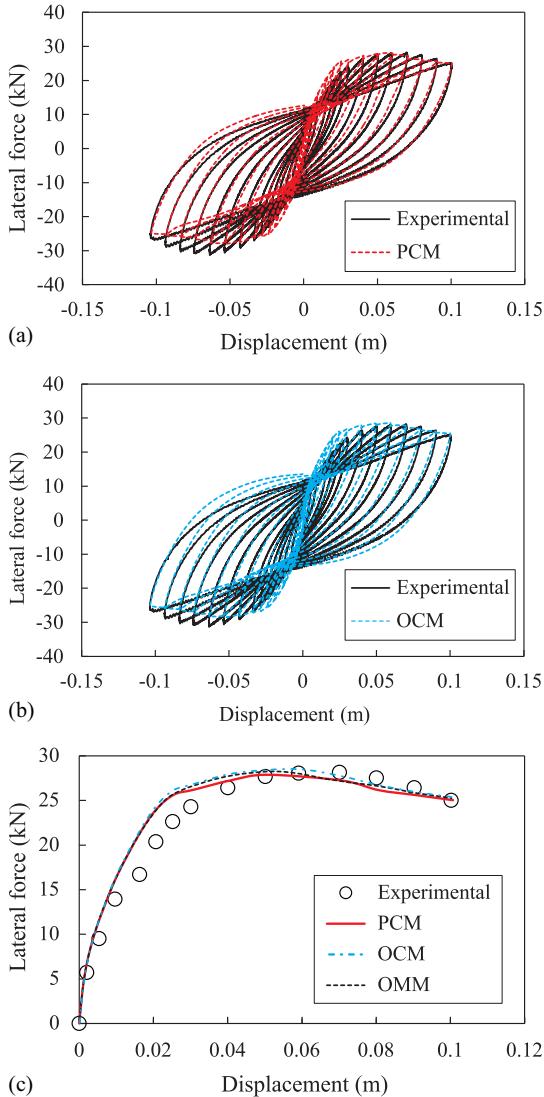
Fig. 5. Comparison of experimentally measured and numerically predicted lateral force-displacement results: (a) cyclic response predicted by PCM; (b) cyclic response predicted by OCM; and (c) backbone curve for positive displacements.
(Paragraph Translate)本段译文
图5. 实验测量与数值预测侧向力-位移结果的比较:(a) PCM预测的循环响应;(b) OCM预测的循环响应;(c) 正位移的骨架曲线。Fig. 6 compares the experimentally measured and numerically predicted pile curvatures. As reported in Zhou et al. (2021a)62, the experimental values of the curvatures along the piles were obtained from strain gauges (identified by circles in Fig. 6), except for the values at the pile heads for displacement values of 30 and 50~\mathrm{mm} which were obtained from the data measured by linear potentiometers (identified by crosses in Fig. 6). To compare consistent experimental and numerical values, the numerical values of the curvature were obtained as the cross-sectional curvatures at the location of the strain gauges for the experimental curvatures obtained by using the strain gauges, whereas they were obtained as the average curvature for the finite elements corresponding to the length of the linear potentiometers for the experimental curvature obtained by using the linear potentiometers. To quantify the accuracy of the different numerical results, Table 6 reports the normalized root mean squared error (Rizzo et al. 2018)47 for different displacement levels, which is calculated as follows:
(Paragraph Translate)本段译文
图6比较了实验测量和数值预测的桩身曲率。正如 Zhou 等人 (2021a)[^62] 所报道的,沿桩身的曲率实验值通过应变计(在图6中以圆形标识)获得,除了位移为30和 $50~\mathrm{mm}$ 时桩头处的数值是通过线性电位计(在图6中以交叉标识)测量的数据获得的。为了比较一致的实验值和数值值,当实验曲率通过应变计获得时,数值曲率值取自应变计位置处的截面曲率;而当实验曲率通过线性电位计获得时,数值曲率值取自与线性电位计长度对应的有限元的平均曲率。为了量化不同数值结果的准确性,表6报告了不同位移水平下的归一化均方根误差(Rizzo 等人 2018)[^47],其计算公式如下:![Comparison of experimentally measured and numerically predicted pile curvatures. [Note: Exp. (s.g.) = experimental values obtained from strain gauges, Exp. (l.p.) = experimental values obtained from linear potentiometers.]](/upload/5F0FF7~1.JPG)
Fig. 6. Comparison of experimentally measured and numerically predicted pile curvatures. [Note: Exp. (s.g.) = experimental values obtained from strain gauges, Exp. (l.p.) = experimental values obtained from linear potentiometers.]
(Paragraph Translate)本段译文
图6. 实验测量与数值预测桩身曲率的比较。[注:Exp. (s.g.) = 应变计获得的实验值,Exp. (l.p.) = 线性电位计获得的实验值。]where \phi_{\mathrm{exp},i} and \phi_{FE,i} = experimentally measured and numerically predicted pile curvatures, respectively, at location i = 1 2, ..., N along the pile; N = total number of the experimental curvature data points collected along a given pile; and \mathrm{FE} = \mathrm{PCM} OCM,or \mathrm{OMM} = considered FE model. It is observed that the predicted pile curvatures by the PCM and OMM are almost identical (i.e., |\epsilon_{\mathrm{PCM}} - \epsilon_{\mathrm{OMM}}|\leq 2.6\% for all considered displacement levels and all pile rows) and present a good agreement with the experimental results (i.e., 2.1\% \leq \epsilon_{\mathrm{PCM}}\leq 10.2\% and 2.7\% \leq \epsilon_{\mathrm{OMM}}\leq 10.0\%). When the pile group was subjected to
(Paragraph Translate)本段译文
其中 $\phi_{\mathrm{exp},i}$ 和 $\phi_{FE,i} =$ 分别为沿桩身位置 $i = 1, 2, \ldots, N$ 处的实验测量和数值预测的桩身曲率;$N =$ 沿给定桩收集的实验曲率数据点的总数;$\mathrm{FE} = \mathrm{PCM}$ OCM 或 $\mathrm{OMM} =$ 所考虑的有限元模型。结果表明,PCM 和 OMM 预测的桩身曲率几乎相同(即,对于所有考虑的位移水平和所有桩排,其绝对误差 $|\epsilon_{\mathrm{PCM}} - \epsilon_{\mathrm{OMM}}|\leq 2.6\%$),并且与实验结果吻合良好(即 $2.1\% \leq \epsilon_{\mathrm{PCM}}\leq 10.2\%$ 和 $2.7\% \leq \epsilon_{\mathrm{OMM}}\leq 10.0\%)$。当桩群受到Table 6. Normalized root-mean-squared error for pile curvatures at different lateral displacements
| Displacement (mm) | FE | Pile location | ||
|---|---|---|---|---|
| Leading (%) | Middle (%) | Trailing (%) | ||
| 10 | PCM | 8.9 | 10.2 | 9.2 |
| OCM | 5.6 | 12.4 | 12.2 | |
| OMM | 9.5 | 10.0 | 9.0 | |
| 30 | PCM | 8.4 | 5.9 | 2.1 |
| OCM | 10.0 | 9.7 | 6.9 | |
| OMM | 8.2 | 3.8 | 4.7 | |
| 50 | PCM | 7.6 | 7.3 | 3.6 |
| OCM | 9.9 | 8.9 | 8.3 | |
| OMM | 7.5 | 6.8 | 2.7 |
(Paragraph Translate)本段译文
表6. 不同侧向位移下桩身曲率的归一化均方根误差| 位移 (mm) | FE | 桩位置 | ||
|---|---|---|---|---|
| 前排 (%) | 中排 (%) | 后排 (%) | ||
| 10 | PCM | 8.9 | 10.2 | 9.2 |
| OCM | 5.6 | 12.4 | 12.2 | |
| OMM | 9.5 | 10.0 | 9.0 | |
| 30 | PCM | 8.4 | 5.9 | 2.1 |
| OCM | 10.0 | 9.7 | 6.9 | |
| OMM | 8.2 | 3.8 | 4.7 | |
| 50 | PCM | 7.6 | 7.3 | 3.6 |
| OCM | 9.9 | 8.9 | 8.3 | |
| OMM | 7.5 | 6.8 | 2.7 |
cyclic loads, the PCM provided better predictions of the pile curvatures than the OCM, with \epsilon_{\mathrm{PCM}} < \epsilon_{\mathrm{OCM}}, except for leading piles at 10 \mathrm{mm} displacement (for which \epsilon_{\mathrm{PCM}} = 8.9\% and \epsilon_{\mathrm{OCM}} = 5.6\%). In particular, the OCM underestimates the curvature in the belowground plastic hinge regions and overestimates the embedded depth of the plastic hinge for the leading piles, whereas it overestimates the curvature in the belowground plastic hinge regions and underestimates the embedded depth of the plastic hinge for the trailing piles.
(Paragraph Translate)本段译文
循环荷载作用时,PCM 对桩身曲率的预测优于 OCM,除了在 $10 \mathrm{mm}$ 位移处的前排桩(此时 $\epsilon_{\mathrm{PCM}} = 8.9\%$,$\epsilon_{\mathrm{OCM}} = 5.6\%$)外,其他情况下 $\epsilon_{\mathrm{PCM}} < \epsilon_{\mathrm{OCM}}$。具体而言,OCM 低估了前排桩地下塑性铰区域的曲率,并高估了塑性铰的埋深;而对于后排桩,它高估了地下塑性铰区域的曲率,并低估了塑性铰的埋深。Parametric Sensitivity Analysis of Pile Group Foundations in Sandy Soils
(Paragraph Translate)本段译文
# 砂土中桩群基础的参数敏感性分析Parametric Study Matrix
(Paragraph Translate)本段译文
# 参数研究矩阵This study presented results of an in-depth parametric analysis to quantify the seismic performance sensitivity of scoured pile group foundations. The parametric analysis was based on the validated FE modeling method for pile group response under lateral
(Paragraph Translate)本段译文
本研究 प्रस्तुत an in-depth parametric analysis to quantify the seismic performance sensitivity of scoured pile group foundations. 参数分析基于已验证的侧向荷载下桩群响应的有限元建模方法。loading and monotonic pushover analysis. Pushover analysis was preferred over cyclic analysis to reduce the computational effort and because the validation results presented in the previous section of this paper showed that both PCM and OMM produce practically identical global and local responses that are in good agreement with experimental results.
(Paragraph Translate)本段译文
加载和单调推覆分析。推覆分析优于循环分析,因为它能减少计算量,并且本文上一节中提出的验证结果表明,PCM和OMM在全局和局部响应方面产生了几乎相同的结果,与实验结果吻合良好。Eleven modeling parameters were investigated in this study: seven geometric parameters, i.e., pile configuration (P.C.), pile length (L_{p}), pile diameter (D), pile center-to-center spacing (S), scour depth (L_{a}), longitudinal steel reinforcement ratio (\rho_{l}), and transverse steel reinforcement ratio (\rho_{s}); one loading parameter, i.e., axial load ratio of the piles (\eta); two material parameters, i.e., concrete strength (f_{c}) and yield strength of the steel reinforcement (f_{y}); and one soil parameter, i.e., relative density of sand (D_r). A central composite design method was used to select the parameter combinations to be investigated, as shown in Table 7. For these combinations, C0 was selected as the central point, and every other combination was obtained by varying one parameter at a time, with three different values for each parameter. These parameter values were selected based on typical values encountered in practice and in the literature (Aviram et al. 2008)10; (Blanco et al. 2019)13; (Das 2002)23; (Jones et al. 2002)30. As a result, 23 cases are considered in this study.
(Paragraph Translate)本段译文
本研究调查了11个建模参数:七个几何参数,即桩配置 $(P.C.)$、桩长 $(L_{p})$、桩径 $(D)$、桩中心距 $(S)$、冲刷深度 $(L_{a})$、纵向钢筋配筋率 $(\rho_{l})$ 和横向钢筋配筋率 $(\rho_{s})$;一个荷载参数,即桩的轴向荷载比 $(\eta)$;两个材料参数,即混凝土强度 $(f_{c})$ 和钢筋屈服强度 $(f_{y})$;以及一个土体参数,即砂土的相对密度 $(D_r)$。采用中心复合设计方法来选择要研究的参数组合,如表7所示。对于这些组合,C0 被选为中心点,而其他每个组合都是通过一次改变一个参数获得的,每个参数有三个不同的值。这些参数值是根据实践和文献中遇到的典型值选择的[^10];[^13];[^23];[^30]。因此,本研究共考虑了23个案例。Table 7. Parameter matrix and studied cases
| Case ID | P.C. | Lp(D) | D(m) | S(D) | La(D) | \rhol | \rhos | \eta | fc(Mpa) | fy(MPa) | Dr(%) |
|---|---|---|---|---|---|---|---|---|---|---|---|
| C0 | 2×3 | 35 | 1.2 | 3 | 5 | 0.016 | 0.012 | 0.2 | 50 | 420 | 50 |
| C1 | 2×2 | 35 | 1.2 | 3 | 5 | 0.016 | 0.012 | 0.2 | 50 | 420 | 50 |
| C2 | 3×3 | 35 | 1.2 | 3 | 5 | 0.016 | 0.012 | 0.2 | 50 | 420 | 50 |
| C3 | 2×3 | 30 | 1.2 | 3 | 5 | 0.016 | 0.012 | 0.2 | 50 | 420 | 50 |
| C4 | 2×3 | 40 | 1.2 | 3 | 5 | 0.016 | 0.012 | 0.2 | 50 | 420 | 50 |
| C5 | 2×3 | 35 | 0.6 | 3 | 5 | 0.016 | 0.012 | 0.2 | 50 | 420 | 50 |
| C6 | 2×3 | 35 | 1.8 | 3 | 5 | 0.016 | 0.012 | 0.2 | 50 | 420 | 50 |
| C7 | 2×3 | 35 | 1.2 | 2.5 | 5 | 0.016 | 0.012 | 0.2 | 50 | 420 | 50 |
| C8 | 2×3 | 35 | 1.2 | 5 | 5 | 0.016 | 0.012 | 0.2 | 50 | 420 | 50 |
| C9 | 2×3 | 35 | 1.2 | 3 | 3 | 0.016 | 0.012 | 0.2 | 50 | 420 | 50 |
| C10 | 2×3 | 35 | 1.2 | 3 | 7 | 0.016 | 0.012 | 0.2 | 50 | 420 | 50 |
| C11 | 2×3 | 35 | 1.2 | 3 | 5 | 0.008 | 0.012 | 0.2 | 50 | 420 | 50 |
| C12 | 2×3 | 35 | 1.2 | 3 | 5 | 0.024 | 0.012 | 0.2 | 50 | 420 | 50 |
| C13 | 2×3 | 35 | 1.2 | 3 | 5 | 0.016 | 0.006 | 0.2 | 50 | 420 | 50 |
| C14 | 2×3 | 35 | 1.2 | 3 | 5 | 0.016 | 0.018 | 0.2 | 50 | 420 | 50 |
| C15 | 2×3 | 35 | 1.2 | 3 | 5 | 0.016 | 0.012 | 0.1 | 50 | 420 | 50 |
| C16 | 2×3 | 35 | 1.2 | 3 | 5 | 0.016 | 0.012 | 0.3 | 50 | 420 | 50 |
| C17 | 2×3 | 35 | 1.2 | 3 | 5 | 0.016 | 0.012 | 0.2 | 30 | 420 | 50 |
| C18 | 2×3 | 35 | 1.2 | 3 | 5 | 0.016 | 0.012 | 0.2 | 70 | 420 | 50 |
| C19 | 2×3 | 35 | 1.2 | 3 | 5 | 0.016 | 0.012 | 0.2 | 50 | 280 | 50 |
| C20 | 2×3 | 35 | 1.2 | 3 | 5 | 0.016 | 0.012 | 0.2 | 50 | 520 | 50 |
| C21 | 2×3 | 35 | 1.2 | 3 | 5 | 0.016 | 0.012 | 0.2 | 50 | 420 | 40 |
| C22 | 2×3 | 35 | 1.2 | 3 | 5 | 0.016 | 0.012 | 0.2 | 50 | 420 | 60 |
Note: The boldface values for each parameter denote the middle, lower, and upper bounds, respectively.
(Paragraph Translate)本段译文
表7. 参数矩阵与研究案例| 案例ID | 桩配置 | Lp(D) | D(m) | S(D) | La(D) | \rhol | \rhos | \eta | fc(Mpa) | fy(MPa) | Dr(%) |
|---|---|---|---|---|---|---|---|---|---|---|---|
| C0 | 2×3 | 35 | 1.2 | 3 | 5 | 0.016 | 0.012 | 0.2 | 50 | 420 | 50 |
| C1 | 2×2 | 35 | 1.2 | 3 | 5 | 0.016 | 0.012 | 0.2 | 50 | 420 | 50 |
| C2 | 3×3 | 35 | 1.2 | 3 | 5 | 0.016 | 0.012 | 0.2 | 50 | 420 | 50 |
| C3 | 2×3 | 30 | 1.2 | 3 | 5 | 0.016 | 0.012 | 0.2 | 50 | 420 | 50 |
| C4 | 2×3 | 40 | 1.2 | 3 | 5 | 0.016 | 0.012 | 0.2 | 50 | 420 | 50 |
| C5 | 2×3 | 35 | 0.6 | 3 | 5 | 0.016 | 0.012 | 0.2 | 50 | 420 | 50 |
| C6 | 2×3 | 35 | 1.8 | 3 | 5 | 0.016 | 0.012 | 0.2 | 50 | 420 | 50 |
| C7 | 2×3 | 35 | 1.2 | 2.5 | 5 | 0.016 | 0.012 | 0.2 | 50 | 420 | 50 |
| C8 | 2×3 | 35 | 1.2 | 5 | 5 | 0.016 | 0.012 | 0.2 | 50 | 420 | 50 |
| C9 | 2×3 | 35 | 1.2 | 3 | 3 | 0.016 | 0.012 | 0.2 | 50 | 420 | 50 |
| C10 | 2×3 | 35 | 1.2 | 3 | 7 | 0.016 | 0.012 | 0.2 | 50 | 420 | 50 |
| C11 | 2×3 | 35 | 1.2 | 3 | 5 | 0.008 | 0.012 | 0.2 | 50 | 420 | 50 |
| C12 | 2×3 | 35 | 1.2 | 3 | 5 | 0.024 | 0.012 | 0.2 | 50 | 420 | 50 |
| C13 | 2×3 | 35 | 1.2 | 3 | 5 | 0.016 | 0.006 | 0.2 | 50 | 420 | 50 |
| C14 | 2×3 | 35 | 1.2 | 3 | 5 | 0.016 | 0.018 | 0.2 | 50 | 420 | 50 |
| C15 | 2×3 | 35 | 1.2 | 3 | 5 | 0.016 | 0.012 | 0.1 | 50 | 420 | 50 |
| C16 | 2×3 | 35 | 1.2 | 3 | 5 | 0.016 | 0.012 | 0.3 | 50 | 420 | 50 |
| C17 | 2×3 | 35 | 1.2 | 3 | 5 | 0.016 | 0.012 | 0.2 | 30 | 420 | 50 |
| C18 | 2×3 | 35 | 1.2 | 3 | 5 | 0.016 | 0.012 | 0.2 | 70 | 420 | 50 |
| C19 | 2×3 | 35 | 1.2 | 3 | 5 | 0.016 | 0.012 | 0.2 | 50 | 280 | 50 |
| C20 | 2×3 | 35 | 1.2 | 3 | 5 | 0.016 | 0.012 | 0.2 | 50 | 520 | 50 |
| C21 | 2×3 | 35 | 1.2 | 3 | 5 | 0.016 | 0.012 | 0.2 | 50 | 420 | 40 |
| C22 | 2×3 | 35 | 1.2 | 3 | 5 | 0.016 | 0.012 | 0.2 | 50 | 420 | 60 |
注:每个参数的粗体值分别表示中值、下限和上限。
The modeling details and the constitutive model of the cover concrete and the longitudinal steel rebars were identical to those used in the FE model of the quasi-static test. The elastic modulus and strain hardening ratio of the reinforcement were 201 GPa and 0.83\% (Zhou et al. 2022a)63, respectively. To model steel reinforcement with spirals, the core concrete of the piles was modeled by using the uniaxial material Concrete04 available in OpenSees, which corresponds to the Mander model with zero tension strength (Mander et al. 1988)38. Table 8 summarizes the values of the constitutive parameters used in the parametric study to model the core concrete. The modeling approach used here for the lateral and vertical soil-pile interaction was identical to that described for the OMM.
(Paragraph Translate)本段译文
覆盖层混凝土和纵向钢筋的建模细节和本构模型与准静态试验的有限元模型中使用的相同。钢筋的弹性模量和应变硬化比分别为201 GPa和$0.83\%$ (Zhou et al. 2022a)[^63]。为了模拟螺旋配筋的钢筋,桩的混凝土核心采用OpenSees中可用的单轴材料Concrete04进行建模,该材料对应于具有零抗拉强度的Mander模型[^38]。表8总结了参数研究中用于模拟核心混凝土的本构参数值。这里用于侧向和竖向土-桩相互作用的建模方法与OMM中描述的相同。Ductility Development and Performance Limit States of Scoured Pile Groups
(Paragraph Translate)本段译文
# 冲刷桩群的延性发展和性能极限状态The piles in a scoured pile group form a frame-like structure due to the constraints imposed by the surrounding soil and the pile-cap connection. Multiple plastic hinges can develop on the pile shafts, both above and below ground levels, when subjected to lateral loads (Liu et al. 2020)36; (Wang et al. 2016)56; (Zhou et al. 2021a)62. The plastic hinge development can be used to define limit states for both load and resistance factor design and performance-based design and to assess the safety and need for retrofit of damaged bridges after an earthquake event. Based on the structural behavior identified in the existing literature (Blanco et al. 2019)13; (Liu et al. 2020)36; (Wang et al. 2016)56; (Zhou et al. 2021a)62, five performance limit states for a pile group are considered in this study: (1) first aboveground yielding (FAY), corresponding to the first yielding of any longitudinal steel reinforcement in the pile group, which for scoured piles is generally located at the interface between cap and leading piles; (2) first belowground yielding (FBY), corresponding to the easy-to-repair limit state introduced by Blanco
(Paragraph Translate)本段译文
冲刷桩群中的桩由于周围土体和桩帽连接施加的约束而形成框架状结构。当承受侧向荷载时,桩身在地上和地下均可能发展多个塑性铰[^36];[^56];[^62]。塑性铰的发展可用于定义荷载和阻力系数设计以及基于性能设计中的极限状态,并评估地震事件后受损桥梁的安全性及加固需求。基于现有文献中识别的结构行为[^13];[^36];[^56];[^62],本研究考虑了桩群的五个性能极限状态:(1) 首个地上屈服(FAY),对应于桩群中任何纵向钢筋的首次屈服,对于冲刷桩,通常位于桩帽与前排桩的界面处;(2) 首个地下屈服(FBY),对应于Blanco等人引入的易修复极限状态Table 8. Core concrete parameters used in the studied cases
| Case ID | Peak strength (MPa) | Strain at peak strength | Ultimate strain |
|---|---|---|---|
| C0-C12, C15, C16, C21, C22 | 64.9 | 0.00498 | 0.0167 |
| C13 | 57.8 | 0.00357 | 0.0104 |
| C14 | 71.3 | 0.00627 | 0.0231 |
| C17 | 44.0 | 0.00667 | 0.0252 |
| C18 | 85.3 | 0.00419 | 0.0131 |
| C19 | 60.3 | 0.00406 | 0.0125 |
| C20 | 68.0 | 0.00561 | 0.0197 |
(Paragraph Translate)本段译文
表8. 研究案例中使用的核心混凝土参数| 案例ID | 峰值强度 (MPa) | 峰值强度应变 | 极限应变 |
|---|---|---|---|
| C0-C12, C15, C16, C21, C22 | 64.9 | 0.00498 | 0.0167 |
| C13 | 57.8 | 0.00357 | 0.0104 |
| C14 | 71.3 | 0.00627 | 0.0231 |
| C17 | 44.0 | 0.00667 | 0.0252 |
| C18 | 85.3 | 0.00419 | 0.0131 |
| C19 | 60.3 | 0.00406 | 0.0125 |
| C20 | 68.0 | 0.00561 | 0.0197 |
et al. (2019)13, so called because the pile damage observed before reaching this level is limited to only the aboveground portion of the piles, which is easily accessible for postearthquake inspection and repair; (3) peak lateral strength (PLS), beyond which lateral strength degradation initiates; (4) severe structural damage (SSD), which is identified by the core concrete crushing or the rupture of the longitudinal steel reinforcement in any pile within the pile group, whichever occurs first; and (5) ultimate residual strength (URS), defined here as a 15\% reduction of the lateral strength from its peak value (Ataei and Padgett 2012)9; (Shen et al. 2021)51. A multiple-level displacement ductility index for a pile group is defined here as follows:
where \Delta_{i} = horizontal displacement of the cap center corresponding to any specific damage state i = 1,2,3,4, and 5 (i.e., FAY, FBY, PLS, SSD, and URS limit states, respectively).
(Paragraph Translate)本段译文
等人 (2019)[^13] 提出的,之所以这样称呼,是因为在该水平之前观察到的桩损坏仅限于桩的地上部分,易于进行震后检查和修复;(3) 峰值侧向强度(PLS),超过该点后侧向强度开始退化;(4) 严重结构损伤(SSD),其特征是桩群中任何一根桩的核心混凝土压碎或纵向钢筋断裂,以先发生者为准;(5) 极限残余强度(URS),此处定义为侧向强度从峰值降低 $15\%$ (Ataei and Padgett 2012)[^9]; (Shen et al. 2021)[^51]。桩群的多级位移延性指数在此定义如下:其中 \Delta_{i} = 桩帽中心对应的水平位移,对应于任何特定损伤状态 i = 1,2,3,4, 和 5(即 FAY, FBY, PLS, SSD 和 URS 极限状态)。
Fig. 7 plots the backbone curves with markers to identify the displacements corresponding to the considered limit states for all 23 cases. For the 2 \times 3 pile groups, the FAY and FBY occur on the leading piles, consistent with the findings of previous experimental studies (Liu et al. 2020)36; (Zhou et al. 2021a)62, whereas the FAY and FBY occur on the trailing pile for the 2 \times 2 pile group (i.e., case C1). The ductility development for the 3 \times 3 pile groups is very similar to that for the 2 \times 3 pile groups, with a lateral resistance equal to 1.5 times that of the corresponding 2 \times 3 pile groups, as the pile group effect is identical for these two cases. For all the considered cases, the SSD corresponds to the condition of concrete crushing at the head of the leading piles, which always occurs before the rupture of the longitudinal steel reinforcement. The SSD limit state always occurs before the URS limit state, except for cases C11 and C14. This phenomenon is observed because (1) for C11, the low longitudinal steel reinforcement ratio induces a rapid postpeak strength reduction, thus reaching the URS limit state before the core concrete can reach its ultimate strain; and (2) for C14, the high transverse reinforcement ratio significantly increases the ultimate strain of the core concrete, thus delaying its crushing limit state.
(Paragraph Translate)本段译文
图7绘制了骨架曲线,并用标记标识了所有23个案例对应于所考虑极限状态的位移。对于 $2 \times 3$ 桩群,FAY 和 FBY 发生在主导桩上,这与之前实验研究的结果一致[^36];[^62],而对于 $2 \times 2$ 桩群(即案例 C1),FAY 和 FBY 发生在后排桩上。对于 $3 \times 3$ 桩群的延性发展与 $2 \times 3$ 桩群非常相似,其侧向阻力是相应 $2 \times 3$ 桩群的1.5倍,因为这两种情况的桩群效应是相同的。对于所有考虑的案例,SSD 对应于主导桩头混凝土压碎的情况,这总是发生在纵向钢筋断裂之前。SSD 极限状态总是发生在 URS 极限状态之前,除了案例 C11 和 C14。观察到这种现象的原因是 (1) 对于 C11,较低的纵向钢筋配筋率导致峰后强度迅速下降,从而在核心混凝土达到其极限应变之前达到 URS 极限状态;(2) 对于 C14,较高的横向配筋率显著增加了核心混凝土的极限应变,从而延迟了其压碎极限状态。The pile length has a negligible impact on the lateral resistance of the pile group and the displacements corresponding to the different limit states. It is noted that this conclusion is valid here because the piles behave as deep foundations without uplift. As expected, the lateral strength of a pile group significantly increases with increasing pile diameters. More specifically, the peak lateral strength of the studied pile groups is equal to 1,511, 7,527, and 18,788\mathrm{kN} for D = 0.6, 1.2, and 1.8\mathrm{m}, respectively. The pile spacing has a slight effect on the peak lateral strength and the limit state displacements of a pile group. An increasing scour depth produces a reduction of the peak lateral strength of the pile groups and an increase of the displacement values corresponding to different limit states. In particular, the peak lateral strength of the pile groups is equal to 9,988, 7,527, and 5,860\mathrm{kN} for a scour depth equal to 3D, 5D, and 7D (with D = 1.2\mathrm{m}), respectively. Increasing the longitudinal steel reinforcement ratio can enhance the lateral resistance of a pile group and increase the displacement corresponding to the first three limit states (FAY, FBY, and PLS). By contrast, the transverse steel reinforcement ratio has a negligible effect on the global lateral load-displacement response of the pile group before PLS, but it becomes significant in controlling the strength degradation after the peak. An increasing axial load ratio slightly increases the peak lateral strength of a pile group; however, it also accelerates the crushing of the core concrete and triggers a rapid degradation of the lateral strength, which is an undesirable behavior for structures subjected to earthquake excitations. Increasing the concrete strength can improve the lateral strength of a pile group, but it results in a more rapid degradation of the lateral strength. By contrast, increasing the yield strength of steel reinforcement can delay the lateral strength degradation after peak, but it is not the most desirable approach for improving the lateral resistance of a pile group. The relative density of sand has very small effects on the peak lateral strength and the limit state displacements of a pile group.
(Paragraph Translate)本段译文
桩长对桩群的侧向阻力以及不同极限状态对应的位移影响可忽略不计。需要注意的是,这一结论在此处是有效的,因为桩表现为无上拔的深基础。正如预期,桩群的侧向强度随桩径的增加而显著增加。更具体地说,对于 $D = 0.6$、1.2 和 $1.8\mathrm{m}$ 的桩群,其峰值侧向强度分别为 1,511、7,527 和 $18,788\mathrm{kN}$。桩间距对桩群的峰值侧向强度和极限状态位移有轻微影响。冲刷深度的增加会导致桩群峰值侧向强度的降低,并增加不同极限状态对应的位移值。特别是,当冲刷深度等于 $3D$、$5D$ 和 $7D$(桩径 $D = 1.2\mathrm{m}$)时,桩群的峰值侧向强度分别为 9,988、7,527 和 $5,860\mathrm{kN}$。增加纵向钢筋配筋率可以增强桩群的侧向阻力,并增加前三个极限状态(FAY、FBY和PLS)对应的位移。相比之下,横向钢筋配筋率对桩群在PLS之前的整体侧向荷载-位移响应影响可忽略不计,但在峰值后控制强度退化方面变得显著。轴向荷载比的增加会轻微增加桩群的峰值侧向强度;然而,它也会加速核心混凝土的压碎,并引发侧向强度的快速退化,这对于承受地震激励的结构来说是一种不良行为。增加混凝土强度可以提高桩群的侧向强度,但会导致侧向强度更快的退化。相比之下,增加钢筋屈服强度可以延迟峰值后的侧向强度退化,但这并不是提高桩群侧向阻力最理想的方法。砂土的相对密度对桩群的峰值侧向强度和极限状态位移影响非常小。Sensitivity Rankings of the Studied Parameters
(Paragraph Translate)本段译文
# 所研究参数的敏感性排名The sensitivity rankings of the 11 parameters considered in this study in terms of seismic performance of a scoured pile group foundation were investigated by using the tornado diagram method (Barbato et al. 2010)12. The seismic performance of a scoured pile group is assessed with respect to three aspects, i.e.: (1) global resistance to an earthquake excitation; (2) residual displacement corresponding to the FBY limit state, which is directly related to the postearthquake repair costs; and (3) ductility capacity. The parameter sensitivity for a given response R is quantified by the total relative swing, sw_{R}, which is defined as follows:
where R_{0} = value of the response quantity when the considered parameter is equal to the middle (reference) value; R^{(-)} and R^{(+)} = values of the response quantity when the considered parameter is assumed to equal to the lower and upper bounds, respectively, which are given in Table 7; and sw_{R}^{(-)} = \Delta R^{(-)} / R_{0} and sw_{R}^{(+)} = \Delta R^{(+)} / R_{0} = lower and upper relative swing, respectively, which are also referred to as one-side relative swings hereinafter. These calculated total relative swings are sorted from high to low values and plotted from top to bottom to form the corresponding tornado diagram.
(Paragraph Translate)本段译文
本研究利用龙卷风图法[^12]调查了所考虑的11个参数对冲刷桩群基础抗震性能的敏感性排名。冲刷桩群的抗震性能从三个方面进行评估,即:(1) 对地震激励的整体抵抗力;(2) 对应于FBY极限状态的残余位移,这与震后修复成本直接相关;(3) 延性能力。给定响应$R$的参数敏感性由总相对摆幅$sw_{R}$量化,其定义如下:其中 R_{0} = 当所考虑的参数等于中间(参考)值时的响应量值;R^{(-)} 和 R^{(+)} = 当所考虑的参数分别假定为等于下限和上限值时的响应量值,这些值在表 7 中给出;sw_{R}^{(-)} = \Delta R^{(-)} / R_{0} 和 sw_{R}^{(+)} = \Delta R^{(+)} / R_{0} = 分别为下限和上限相对摆幅,在下文中也称为单侧相对摆幅。这些计算出的总相对摆幅按从高到低的顺序排列,并从上到下绘制,以形成相应的龙卷风图。
The global resistance of a pile group was quantified by three indexes, i.e. (1) the lateral strength at the FAY limit state, referred to as yield strength of a pile group hereinafter, beyond which the yielding of a pile group initiates; (2) the strength enhancement coefficient of a pile group after yielding, denoted SE, and defined as follows:
where F_{\mathrm{FAY}} and F_{\mathrm{PLS}} = lateral strengths at FAY and PLS limit states, respectively, which represents the capacity of a pile group after yielding; and (3) the normalized strength degradation rate after peak, SDR, which is proposed in this study for the first time and is defined as the ratio between the postyield stiffness and the
(Paragraph Translate)本段译文
桩群的整体抵抗力由三个指标量化,即 (1) FAY极限状态下的侧向强度,以下称为桩群的屈服强度,超过该强度桩群开始屈服;(2) 屈服后桩群的强度增强系数,表示为 SE,定义如下:其中 F_{\mathrm{FAY}} 和 F_{\mathrm{PLS}} = 分别是 FAY 和 PLS 极限状态下的侧向强度,代表桩群屈服后的承载力;(3) 首次在本研究中提出的峰值后归一化强度退化率 SDR,其定义为屈服后刚度与
secant stiffness at yielding of a pile group as follows:
where F_{\mathrm{URS}} = lateral strength at the URS limit state; and \Delta_{\mathrm{FAY}} and \Delta_{\mathrm{URS}} = displacement at the FAY and URS limit states, respectively.
(Paragraph Translate)本段译文
桩群屈服时的割线刚度,定义如下:其中 F_{\mathrm{URS}} = URS 极限状态下的侧向强度;\Delta_{\mathrm{FAY}} 和 \Delta_{\mathrm{URS}} = 分别为 FAY 和 URS 极限状态下的位移。
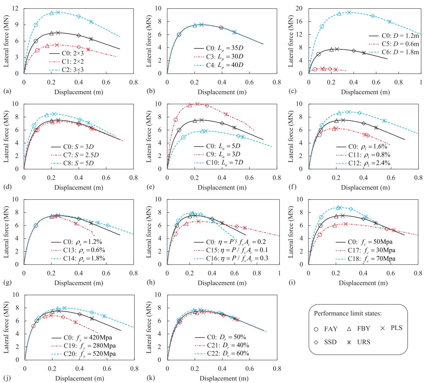
Fig. 7. Sensitivity of lateral capacity to parameter variability: (a) pile configuration; (b) pile length; (c) pile diameter; (d) pile spacing; (e) scour depth; (f) longitudinal steel reinforcement ratio; (g) transverse reinforcement ratio; (h) axial load ratio; (i) concrete strength; (j) yield strength of reinforcements; and (k) soil relative density.
(Paragraph Translate)本段译文
图7. 侧向承载力对参数变异性的敏感性:(a) 桩配置;(b) 桩长;(c) 桩径;(d) 桩间距;(e) 冲刷深度;(f) 纵向钢筋配筋率;(g) 横向配筋率;(h) 轴向荷载比;(i) 混凝土强度;(j) 钢筋屈服强度;(k) 土体相对密度。Fig. 8 shows the sensitivity rankings of the 11 parameters with respect to the global seismic resistance of the studied pile groups. The parameters below the horizontal dashed line have a small effect on the studied response with a maximum one-side relative swing of less than 0.05. It was observed that the yield strength of a pile group is most sensitive to the pile diameter (with a relative swing equal to 2.19), whereas the strength enhancement coefficient and normalized strength degradation rate were most sensitive to the axial load ratio (with a relative swing equal to 0.19 and 0.85, respectively). Increasing the pile diameter could significantly improve the yield strength, raise the strength enhancement coefficient, and delay the strength degradation of a pile group. Increasing the axial load ratio slightly enhanced the yield strength of a pile group, but it considerably accelerated the strength degradation and reduced the strength enhancement coefficient of a pile group, which is an undesirable effect for the scoured pile groups. The scour was also undesirable for a pile group because it significantly weakened the pile group (e.g., the yield strength decreased by 36% in this study when the scour depth increased from 3D to 7D), decreased the strength enhancement coefficient, and accelerated the strength degradation of a pile group. The transverse steel reinforcement ratio had a small effect on the yield strength and the strength enhancement coefficient of a pile group, but it could significantly delay the lateral strength degradation of a pile group after peak strength is reached (with a relative swing equal to 0.73). In addition, the global resistance of a pile group was mostly insensitive to the relative density of sandy soil and the pile length. Compared with the yield strength and the normalized strength degradation rate, the strength enhancement coefficient was relatively stable and showed less sensitivity to the studied parameters because its maximum one-side relative swing was only 0.12.
(Paragraph Translate)本段译文
图8显示了所研究的11个参数对所研究桩群整体抗震性能的敏感性排名。虚线以下参数对所研究响应的影响较小,最大单侧相对摆幅小于0.05。观察到,桩群的屈服强度对桩径最敏感(相对摆幅为2.19),而强度增强系数和归一化强度退化率对轴向荷载比最敏感(相对摆幅分别为0.19和0.85)。增加桩径可以显著提高屈服强度,提高强度增强系数,并延迟桩群的强度退化。增加轴向荷载比略微提高了桩群的屈服强度,但却显著加速了强度退化并降低了桩群的强度增强系数,这对于冲刷桩群来说是一个不利影响。冲刷对桩群也是不利的,因为它显著削弱了桩群(例如,在本研究中当冲刷深度从3D增加到7D时,屈服强度降低了36%),降低了强度增强系数,并加速了桩群的强度退化。横向钢筋配筋率对桩群的屈服强度和强度增强系数影响较小,但它可以显著延迟桩群在达到峰值强度后的侧向强度退化(相对摆幅为0.73)。此外,桩群的整体抵抗力对砂土的相对密度和桩长大多不敏感。与屈服强度和归一化强度退化率相比,强度增强系数相对稳定,对所研究参数的敏感性较低,因为其最大单侧相对摆幅仅为0.12。
Fig. 8. Parameter sensitivity rankings for the global resistance: (a) lateral strength at FAY limit state; (b) strength enhancement coefficient of a pile group after yielding; and (c) normalized strength degradation rate after the peak.
(Paragraph Translate)本段译文
图8. 全局抵抗力的参数敏感性排名:(a) FAY极限状态下的侧向强度;(b) 屈服后桩群的强度增强系数;(c) 峰值后的归一化强度退化率。Fig. 9 presents the parameter sensitivity ranking for the residual displacement of a pile group at FBY limit state (denoted as DR_{\mathrm{FBY}} hereinafter). The residual displacement was obtained by the following two analysis steps using the PCM: (1) load the model to determine the lateral displacement of the pile group at the FBY limit state and (2) unload the model until it reaches a zero-lateral force state. The displacement corresponding to the zero-lateral force state was regarded as the residual displacement of the pile group (Zhou et al. 2021a)62. As shown in Fig. 9, the top five parameters to which the residual displacement of a pile group at the FBY limit state is sensitive are (in decreasing order of importance) (1) axial load ratio, (2) yield strength of the steel reinforcement, (3) longitudinal steel reinforcement ratio, (4) pile diameter, and (5) scour depth in sequence, corresponding to the relative swings of 0.91, 0.54, 0.51, 0.49, and 0.26, respectively. Their increase leads to the increase of the residual displacement of a pile group, which is detrimental to the postearthquake recovery efforts. The pile length and transverse steel reinforcement ratio have less effect on the residual displacement of a pile group corresponding to the FBY state since the maximum one-side relative swing is less than 0.05.
(Paragraph Translate)本段译文
图9展示了桩群在FBY极限状态下残余位移(以下简称 $DR_{\mathrm{FBY}}$)的参数敏感性排名。残余位移是通过PCM的以下两个分析步骤获得的:(1) 对模型加载以确定桩群在FBY极限状态下的侧向位移,以及 (2) 卸载模型直到其达到零侧向力状态。对应于零侧向力状态的位移被视为桩群的残余位移[^62]。如图9所示,影响桩群在FBY极限状态下残余位移的前五个参数(按重要性递减顺序)是:(1) 轴向荷载比,(2) 钢筋屈服强度,(3) 纵向钢筋配筋率,(4) 桩径,以及 (5) 冲刷深度,其相对摆幅分别为0.91、0.54、0.51、0.49和0.26。它们的增加会导致桩群残余位移的增加,这不利于震后恢复工作。桩长和横向钢筋配筋率对桩群在FBY状态下的残余位移影响较小,因为最大单侧相对摆幅小于0.05。
Fig. 9. Parameter sensitivity ranking for the residual displacement at the FBY limit state.
(Paragraph Translate)本段译文
图9. FBY极限状态下残余位移的参数敏感性排名。Fig. 10 shows the sensitivity rankings of the different parameters with respect to the displacement ductility of a pile group at the FBY, PLS, and SSD limit states. The top four parameters to which the FBY displacement ductility of a pile group is sensitive are (in decreasing order of importance) P.C., scour depth, pile center-to-center spacing, and pile diameter. The other remaining seven parameters have a small effect on the FBY displacement ductility since their maximum one-side relative swing is less than 0.05. The 2 \times 3 and 3 \times 3 pile groups present an almost identical FBY displacement ductility since they have the same pile group effect. The axial load ratio affects the most the displacement ductility of a pile group at the PLS and SSD states (with a relative swing equal to 0.55 and 1.18, respectively), but it has a very small impact on the ductility of a pile group at the FBY state (with a relative swing smaller than 0.006). The higher the axial load ratio causes a lower pile group ductility corresponding to PLS and SSD states. The increase in the scour depth reduces the ductility of a pile group at the FBY and PLS states, but it has almost no impact on the ductility of a pile group at the SSD state. Increasing the transverse steel reinforcement ratio improves the ductility of a pile group at the SSD limit state; however, the transverse steel reinforcement ratio has a negligible impact on the ductility of the pile group at the FBY and PLS limit states. The displacement ductility of a pile group is insensitive to the pile length and the relative density of sand.
(Paragraph Translate)本段译文
图10显示了不同参数对桩群在FBY、PLS和SSD极限状态下的位移延性的敏感性排名。影响桩群FBY位移延性的前四个参数(按重要性递减顺序)是桩配置 ($P.C.$)、冲刷深度、桩中心距和桩径。其余七个参数对FBY位移延性的影响较小,因为它们的最大单侧相对摆幅小于0.05。$2 \times 3$ 和 $3 \times 3$ 桩群表现出几乎相同的FBY位移延性,因为它们具有相同的桩群效应。轴向荷载比对桩群在PLS和SSD状态下的位移延性影响最大(相对摆幅分别为0.55和1.18),但对桩群在FBY状态下的延性影响非常小(相对摆幅小于0.006)。轴向荷载比越高,桩群在PLS和SSD状态下对应的延性越低。冲刷深度的增加会降低桩群在FBY和PLS状态下的延性,但对桩群在SSD状态下的延性几乎没有影响。增加横向钢筋配筋率可以提高桩群在SSD极限状态下的延性;然而,横向钢筋配筋率对桩群在FBY和PLS极限状态下的延性影响可忽略不计。桩群的位移延性对桩长和砂土的相对密度不敏感。Considerations for Seismic Performance Improvements
(Paragraph Translate)本段译文
# 抗震性能改进的考虑因素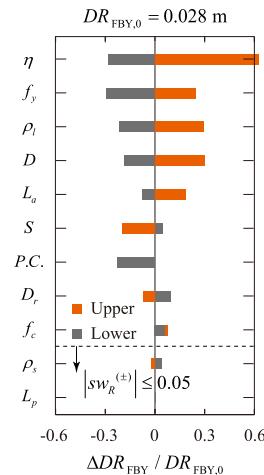
Fig. 10. Parameter sensitivity rankings for the displacement ductility at (a) FBY; (b) PLS; and (c) SSD limit states.
(Paragraph Translate)本段译文
图10. 位移延性在 (a) FBY;(b) PLS;和 (c) SSD 极限状态下的参数敏感性排名。The parametric sensitivity analysis results can be used to provide meaningful recommendations for the seismic design and retrofit of pile group foundations in sandy soils subject to scour effects, as summarized in Table 9. In this table, the plus sign (+) indicates that increasing the corresponding parameter value improves the seismic performance of the pile group (i.e., having a positive effect); the cross mark (\times) represents that the increase of the parameter value deteriorates the performance (i.e., having a negative effect); the horizontal line (-) indicates that the response is not monotonically affected by the parameter; the slash mark (\backslash) indicates that the corresponding parameter has a generally small effect on the seismic performance (i.e., both lower and upper relative swings are less than 0.05). In addition, the marks corresponding to the three parameters affecting the most each considered response are highlighted in bold, and the most important and second most important parameters for each considered response are identified by three and two marks, respectively.
(Paragraph Translate)本段译文
参数敏感性分析结果可用于为受冲刷影响的砂土中桩群基础的抗震设计和改造提供有意义的建议,如表9所示。在此表中,加号 $(+)$ 表示增加相应参数值可改善桩群的抗震性能(即具有积极影响);叉号 $(\times)$ 表示增加参数值会恶化性能(即具有消极影响);横线 $(- )$ 表示响应不受参数的单调影响;斜线 $(\backslash)$ 表示相应参数对抗震性能的影响通常较小(即上下相对摆幅均小于0.05)。此外,对每个考虑的响应影响最大的三个参数对应的标记以粗体突出显示,而每个考虑的响应最重要和次重要的参数分别用三个和两个标记表示。Table 9. Seismic performance variation of a pile group by increasing the parameter value
| Parameter | Description | Increasing yield strength | Increasing SE | Reducing SDR | Reducing DRFBY | Increasing \muFBY |
|---|---|---|---|---|---|---|
| P.C. | Pile configuration | ++ | — | — | — | — |
| Lp | Pile length | \ | \ | \ | \ | \ |
| D | Pile diameter | +++ | + | + | × | × |
| S | Pile center-to-center spacing | — | \ | + | + | — |
| La | Scour depth | × | \ | × | × | ×× |
| \rhol | Longitudinal steel reinforcement ratio | + | + | × | × | \ |
| \rhos | Transverse reinforcement ratio | \ | \ | ++ | \ | \ |
| \eta | Axial load ratio | + | ××× | ××× | ××× | \ |
| fc | Concrete strength | + | ×× | × | — | \ |
| fy | Yield strength of reinforcement | + | \ | \ | ×× | \ |
| Dr | Relative density of sand soil | \ | \ | \ | + | \ |
(Paragraph Translate)本段译文
表9. 桩群抗震性能随参数值增加的变化| 参数 | 描述 | 增加屈服强度 | 增加SE | 降低SDR | 降低DRFBY | 增加\muFBY |
|---|---|---|---|---|---|---|
| P.C. | 桩配置 | ++ | — | — | — | — |
| Lp | 桩长 | \ | \ | \ | \ | \ |
| D | 桩径 | +++ | + | + | × | × |
| S | 桩中心距 | — | \ | + | + | — |
| La | 冲刷深度 | × | \ | × | × | ×× |
| \rhol | 纵向钢筋配筋率 | + | + | × | × | \ |
| \rhos | 横向配筋率 | \ | \ | ++ | \ | \ |
| \eta | 轴向荷载比 | + | ××× | ××× | ××× | \ |
| fc | 混凝土强度 | + | ×× | × | — | \ |
| fy | 钢筋屈服强度 | + | \ | \ | ×× | \ |
| Dr | 砂土相对密度 | \ | \ | \ | + | \ |
In general, increasing the pile diameter is the most efficient measure to improve the seismic performance of a pile group when considering scour effects because it can significantly increase the yield strength and the strength enhancement coefficient of a pile group and reduce the normalized strength degradation rate. Increasing the axial load ratio deteriorates the seismic performance of a scoured pile group because it (1) increases its residual displacement at the FBY state, (2) accelerates the lateral strength degradation after peak strength, and (3) degrades the strength enhancement coefficient of the pile group. Increasing the center-to-center spacing between piles up to 5D has a small positive effect on the seismic performance of a scoured pile group; however, it requires increasing the cap size, resulting in an increase in construction costs. For a deep pile group foundation, the pile length and the relative density of sand have a negligible effect on the seismic performance of the pile group. The transverse reinforcement ratio has a small effect on a pile group's seismic performance before the peak lateral strength is achieved; however, the transverse steel reinforcement must be sufficient to prevent buckling of the longitudinal rebars, which becomes important for large inelastic behavior. The increase in the scour depth generally deteriorates the seismic performance of a pile group.
(Paragraph Translate)本段译文
总的来说,在考虑冲刷效应时,增加桩径是提高桩群抗震性能最有效的措施,因为它能显著提高桩群的屈服强度和强度增强系数,并降低归一化强度退化率。增加轴向荷载比会恶化冲刷桩群的抗震性能,因为它 (1) 增加了桩群在FBY状态下的残余位移,(2) 加速了峰值强度后的侧向强度退化,以及 (3) 降低了桩群的强度增强系数。将桩的中心距增加到 $5D$ 对冲刷桩群的抗震性能有小的积极影响;然而,这需要增加桩帽尺寸,从而导致施工成本增加。对于深桩群基础,桩长和砂土的相对密度对桩群的抗震性能影响可忽略不计。横向配筋率对桩群在达到峰值侧向强度前的抗震性能影响较小;然而,横向钢筋必须足以防止纵向钢筋屈曲,这对于大非弹性行为来说变得很重要。冲刷深度的增加通常会恶化桩群的抗震性能。Conclusions
(Paragraph Translate)本段译文
# 结论This study investigates the seismic performance of scoured pile group foundations. A new practical finite-element modeling approach for the pile group effect is first proposed and validated by the experimental data available in the literature. The proposed approach can simulate the soil resistance difference among different pile rows in a pile group under lateral cyclic loads and provides more accurate local pile curvature results than the currently adopted methodology based on a constant pile group factor. It is also observed that both approaches provide almost identical results in terms of global response quantities, e.g., global lateral force-displacement response, which is in good agreement with existing experimental results. By using the validated model, an in-depth parametric analysis is performed to explore parameter sensitivity with respect to the seismic performance of a pile group foundation. The main findings of this parameter sensitivity analysis are as follows:
(Paragraph Translate)本段译文
本研究调查了冲刷桩群基础的抗震性能。首先提出了一种新的实用有限元建模方法来模拟桩群效应,并利用文献中的实验数据进行了验证。所提出的方法能够模拟桩群在侧向循环荷载作用下不同桩排之间的土体阻力差异,并提供比目前基于恒定桩群系数的方法更准确的局部桩身曲率结果。此外,观察到两种方法在整体响应量方面,例如整体侧向力-位移响应,提供了几乎相同的结果,并且与现有实验结果吻合良好。通过使用已验证的模型,进行了深入的参数分析,以探讨参数对桩群基础抗震性能的敏感性。该参数敏感性分析的主要发现如下:- Scour significantly weakens the seismic capacity of a pile group. It reduces the lateral strength and displacement ductility of a pile group and increases the residual displacement of a pile group at the first belowground yielding (FBY) limit state (corresponding to an easy-to-repair condition).
- Increasing the pile diameter is the most effective measure to improve the seismic performance of a scoured pile group.
(Paragraph Translate)本段译文
1. 冲刷显著削弱了桩群的抗震能力。它降低了桩群的侧向强度和位移延性,并增加了桩群在第一次地下屈服(FBY)极限状态(对应于易于修复的条件)下的残余位移。 2. 增加桩径是提高冲刷桩群抗震性能最有效的措施。Increasing the concrete strength, the yield strength of the steel reinforcement, and the longitudinal steel reinforcement ratio can increase the yield strength of a pile group. However, increasing the yield strength of the steel reinforcement and the longitudinal steel reinforcement ratio can also increase the residual displacement of a pile group at the FBY state. A higher axial load ratio slightly increases the lateral strength of the pile group foundation but also significantly increases its residual displacement, reduces its lateral strength enhancement coefficient, and accelerates its lateral strength degradation. The transverse reinforcement ratio has negligible effects on the yield strength and the residual displacement at the FBY limit state of a pile group; however, a higher transverse reinforcement ratio can decrease the degradation rate of the lateral strength. For a deep foundation in medium-dense sand, the pile length (for values higher than or equal to 30 times the pile diameter), pile spacing (for values smaller than or equal to five times the pile diameter), and relative density of sand (for values between 40\% and 60\%) have negligible effects on seismic performance of a scoured pile group foundation.
(Paragraph Translate)本段译文
增加混凝土强度、钢筋屈服强度和纵向钢筋配筋率可以提高桩群的屈服强度。然而,增加钢筋屈服强度和纵向钢筋配筋率也可能增加桩群在FBY状态下的残余位移。较高的轴向荷载比会略微增加桩群基础的侧向强度,但同时也会显著增加其残余位移,降低其侧向强度增强系数,并加速其侧向强度退化。横向配筋率对桩群在FBY极限状态下的屈服强度和残余位移影响可忽略不计;然而,较高的横向配筋率可以降低侧向强度的退化率。对于中密砂土中的深基础,桩长(当值大于或等于桩径的30倍时)、桩间距(当值小于或等于桩径的5倍时)和砂土相对密度(当值介于$40\%$和$60\%$之间时)对冲刷桩群基础的抗震性能影响可忽略不计。This study uses a set of quasi-static tests available in the literature to validate the proposed pile group effect modeling approach for pile group foundations subjected to lateral cyclic loads. It is recommended to validate this modeling approach also for pile group foundations subjected to dynamic conditions, e.g., seismic shaking. This study mainly focuses on scoured pile groups in homogeneous sand subjected to lateral loads. Further studies are needed to quantify the impacts of different soil conditions and profiles. In addition, future numerical studies should investigate the use of incremental dynamic analysis to develop fragility curves and achieve a better understanding of the ductile behavior and the failure mechanisms of bridges with scoured pile group foundations. It is also suggested to investigate whether the p-multipliers vary with the depth and lateral deformation level of the pile group foundation and how this potential variation affects the performance of a scoured pile group foundation.
(Paragraph Translate)本段译文
本研究利用文献中一组准静态试验来验证所提出的桩群效应建模方法,该方法适用于承受侧向循环荷载的桩群基础。建议对该建模方法进行验证,使其也适用于承受动态条件(例如地震振动)的桩群基础。本研究主要关注均质砂土中承受侧向荷载的冲刷桩群。需要进一步研究以量化不同土体条件和剖面的影响。此外,未来的数值研究应调查使用增量动态分析来开发易损性曲线,并更好地理解带有冲刷桩群基础桥梁的延性行为和破坏机制。还建议研究$p$-乘数是否随桩群基础的深度和侧向变形水平而变化,以及这种潜在变化如何影响冲刷桩群基础的性能。Data Availability Statement
(Paragraph Translate)本段译文
# 数据可用性声明Some or all data, models, or codes that support the findings of this study (including the section analysis executable codes and the force-displacement data for the pile group specimens) are available from the corresponding author upon reasonable request.
(Paragraph Translate)本段译文
支持本研究结果的部分或全部数据、模型或代码(包括截面分析可执行代码和桩群试件的力-位移数据)可根据合理要求向通讯作者获取。Acknowledgments
(Paragraph Translate)本段译文
# 致谢The authors gratefully acknowledge the funding support of this work by the National Natural Science Foundation of China (Grant Nos. 51778469 and 52178155) and the State Key Laboratory of Disaster Reduction in Civil Engineering, Ministry of Science and Technology of China (Grant No. SLDRCE19-B-20). The first author is thankful for the financial support from the China Scholarship Council. Any opinions, findings, and conclusions expressed are those of the authors and do not necessarily reflect those of the sponsoring organizations. Special thanks to Professor Ross W. Boulanger at the University of California, Davis who provided significant suggestions on the modeling of the pile group effect under cyclic loading. All staff members in the Multi-Functional Shaking Table Laboratory of Tongji University at Jiading Campus are also gratefully acknowledged.
(Paragraph Translate)本段译文
作者衷心感谢国家自然科学基金(项目编号51778469和52178155)和中国科学技术部土木工程防灾国家重点实验室(项目编号SLDRCE19-B-20)对本研究的资助。第一作者感谢国家留学基金管理委员会的资助。文中所表达的任何观点、发现和结论均属于作者,不一定反映资助机构的观点。特别感谢加州大学戴维斯分校的Ross W. Boulanger教授,他对循环荷载作用下桩群效应的建模提供了重要建议。同时,衷心感谢同济大学嘉定校区多功能振动台实验室的所有工作人员。References
(Paragraph Translate)本段译文
# 参考文献AASHTO. 2020. AASHTO LRFD bridge design specifications. Washington, DC: AASHTO. ↩ ↩ ↩ ↩
AASHTO. 2022. AASHTO guide specifications for LRFD seismic bridge design. Washington, DC: AASHTO. ↩
Abbas, S. A., W. S. Al Rekabi, and A. H. Al Aboodi. 2016. "Analysis of laterally loaded (2\times 2) square pile groups using finite element method." In Proc., 6th Int. Conf. on Advances in Civil and Structural Engineering, 7-12. Kuala Lumpur, Malaysia: Institute of Research Engineers and Doctors. ↩ ↩
Adeel, M. B., M. A. Jan, M. Aaqib, and D. Park. 2020. "Development of simulation based p-multipliers for laterally loaded pile groups in granular soil using 3D nonlinear finite element model." Appl. Sci. 11 (1): 26. https://doi.org/10.3390/app11010026. ↩ ↩ ↩ ↩
Albusoda, B. S., A. F. Al-Saadi, and A. F. Jasim. 2018. "An experimental study and numerical modeling of laterally loaded regular and finned pile foundations in sandy soils." Comput. Geotech. 102: 102-110. https://doi.org/10.1016/j.comgeo.2018.06.007. ↩ ↩
Alipour, A., and B. Shafri. 2016. "Seismic resilience of transportation networks with deteriorating components." J. Struct. Eng. 142 (8): C4015015. https://doi.org/10.1061/(ASCE)ST.1943-541X.0001399. ↩
Allotey, N., and M. H. El Naggar. 2008. "A numerical study into lateral cyclic nonlinear soil-pile response." Can. Geotech. J. 45 (9): 1268-1281. https://doi.org/10.1139/T08-050. ↩
API (American Petroleum Institute). 2007. Recommended practice for planning, designing and constructing fixed offshore platforms—Working stress design. RP 2A-WSD. Washington, DC: API. ↩ ↩
Ataei, N., and J. E. Padgett. 2012. "Fragility assessment of coastal bridges under hurricane events using enhanced probabilistic capacity models." In Advances in hurricane engineering, edited by C. P. Jones and L. G. Griffis, 691-702. Reston, VA: ASCE. ↩
Aviram, A., K. Mackie, and B. Stojadinovic. 2008. Guidelines of nonlinear analysis of bridge structures in California. PEER 2008/03. Berkeley, CA: Pacific Earthquake Research Center, Univ. of California, Berkeley. ↩
Banerjee, S., J. F. Stanton, and N. M. Hawkins. 1987. "Seismic performance of precast prestressed concrete piles." J. Struct. Eng. 113 (3): 381-396. https://doi.org/10.1061/(ASCE)0733-9445(1987)113:2(381). ↩
Barbato, M., Q. Gu, and J. P. Conte. 2010. "Probabilistic push-over analysis of structural and soil-structure systems." J. Struct. Eng. 136 (11): 1330-1341. https://doi.org/10.1061/(ASCE)ST.1943-541X.0000231. ↩ ↩
Blanco, G., A. Ye, X. Wang, and J. M. Goicolea. 2019. "Parametric push-over analysis on elevated RC pile-cap foundations for bridges in cohesionless soils." J. Bridge Eng. 24 (1): 04018104. https://doi.org/10.1061/(ASCE)BE.1943-5592.0001328. ↩ ↩ ↩ ↩ ↩ ↩ ↩
Boulanger, R. W., C. J. Curras, B. L. Kutter, D. W. Wilson, and A. Abghari. 1999. "Seismic soil-pile-structure interaction experiments and analyses." J. Geotech. Geoenviron. Eng. 125 (9): 750-759. https://doi.org/10.1061/(ASCE)1090-0241(1999)125:9(750). ↩ ↩ ↩ ↩ ↩
Boulanger, R. W., B. L. Kutter, S. J. Brandenberg, P. Singh, and D. Chang. 2003. Pile foundations in liquefied and laterally spreading ground during earthquakes: Centrifuge experiments & analyses. Sacramento, CA: Univ. of California. ↩
Brandenberg, S. J., R. W. Boulanger, B. L. Kutter, and D. Chang. 2007. "Static pushover analyses of pile groups in liquefied and laterally spreading ground in centrifuge tests." J. Geotech. Geoenviron. Eng. 133 (9): 1055-1066. https://doi.org/10.1061/(ASCE)1090-0241(2007)133:9(1055). ↩
Brown, D. A., C. Morrison, and L. C. Reese. 1988. "Lateral load behavior of pile group in sand." J. Geotech. Eng. 114 (11): 1261-1276. https://doi.org/10.1061/(ASCE)0733-9410(1988)114:11(1261). ↩ ↩ ↩ ↩ ↩
Brown, D. A., M. W. O'Neill, M. Hoit, M. McVay, M. H. El Nagger, and S. Chakraborty. 2001. Static and dynamic lateral loading of pile groups. NCHRP Rep. No. 461. Washington, DC: Transportation Research Board, National Research Council. ↩ ↩ ↩
Capers, H. A., C. Huang, J. M. Kulicki, T. Murphy, G. C. Lee, Z. Liang, J. J. Shen, M. Shinozaka, and W. P. Wen. 2013. Principles of multiple-hazard design for highway bridges. Washington, DC: Federal Highway Administration. ↩
Chai, Y. H., and T. C. Hutchinson. 2002. "Flexural strength and ductility of extended pile-shafts II: Experimental study." J. Struct. Eng. 128 (5): 595-602. https://doi.org/10.1061/(ASCE)0733-9445(2002)128:5(595). ↩
Chai, Y. H., and S.-T. Song. 2012. "Inelastic deformation of extended pile-shafts." J. Eng. Mech. 138 (7): 842-852. https://doi.org/10.1061/(ASCE)EM.1943-7889.0000393. ↩ ↩
Christensen, D. S. 2006. Full scale static lateral load test of a 9 pile group in sand. Provo, UT: Brigham Young Univ. ↩ ↩
Das, B. M. 2002. Principles of foundation engineering. Washington, DC: McGraw-Hill. ↩
Fayyazi, M. S., M. Taiebat, W. D. L. Finn, and C. E. Ventura. 2012. "Evaluation of group factor method for analysis of pile groups." In Proc., 15th World Conf. on Earthquake Engineering, Lisbon, Portugal: Sociedade Portuguesa de Engenharia Sismica (SPES). ↩
Filippou, F. C., E. P. Popov, and V. V. Berthot. 1983. Effects of bond deterioration on hysteretic behaviour of reinforced concrete joints. EERC-83/19. Berkeley, CA: Earthquake Engineering Research Center, Univ. of California, Berkeley. ↩
Heidari, M., H. El Nagger, M. Jahanandish, and A. Ghahramani. 2014. "Generalized cyclic p-y curve modeling for analysis of laterally loaded piles." Soil Dyn. Earthquake Eng. 63: 138-149. https://doi.org/10.1016/j.soildyn.2014.04.001. ↩
Hussien, M. N., T. Tobita, S. Iai, and M. Karray. 2016. "Soil-pile-structure kinematic and inertial interaction observed in geotechnical centrifuge experiments." Soil Dyn. Earthquake Eng. 89: 75-84. https://doi.org/10.1016/j.soildyn.2016.08.002. ↩
Hutchinson, T. C., Y. H. Chai, and R. W. Boulanger. 2005. "Simulation of full-scale cyclic lateral load tests on piles." J. Geotech. Geoenviron. Eng. 131 (9): 1172-1175. https://doi.org/10.1061/(ASCE)1090-0241(2005)131:9(1172). ↩
Hutchinson, T. C., Y. H. Chai, R. W. Boulanger, and I. M. Idriss. 2004. "Inelastic seismic response of extended pile-shaft-supported bridge structures." Earthquake Spectra 20 (4): 1057-1080. https://doi.org/10.1193/1.1811614. ↩
Jones, A. L., S. L. Kramer, and P. Arduino. 2002. Estimation of uncertainty in geotechnical properties for performance-based earthquake. PEER 2002/16. Berkeley, CA: Pacific Earthquake Engineering Research Center. ↩
Kawashima, K., Y. Takahashi, H. Ge, Z. Wu, and J. Zhang. 2009. "Reconnaissance report on damage of bridges in 2008 Wenchuan, China, earthquake." J. Earthquake Eng. 13 (7): 965-996. https://doi.org/10.1080/136324609002859169. ↩
Kim, B. T., and G. L. Yoon. 2011. "Laboratory modeling of laterally loaded pile groups in sand." KSCE J. Civ. Eng. 15 (1): 65-75. https://doi.org/10.1007/s12205-011-0924-3. ↩ ↩
Kotthuas, M. 1992. "Zum tragverhalten von horizontal belasteten pfahlreihen aus langen pfahlen in sand." [In German.] Ph.D. thesis, Scriftenreihe des Instituts fur Grundbau, Ruhr-Univ. ↩ ↩
Kramer, S. L., P. Arduino, and S. HyngSuk. 2008. Using OpenSees for performance-based evaluation of bridges on liquefiable soils. Berkeley, CA: Pacific Earthquake Engineering Research Center. ↩
Lemnitzer, A., P. Khalili-Tehrani, E. R. Ahlberg, C. Rha, E. Taciroglu, J. W. Wallace, and J. P. Stewart. 2010. "Nonlinear efficiency of bored pile group under lateral loading." J. Geotech. Geoenviron. Eng. 136 (12): 1673-1685. https://doi.org/10.1061/(ASCE)GT.1943-5606.0000383. ↩ ↩ ↩
Liu, T., X. Wang, and A. Ye. 2020. "Roles of pile group and cap-rotation effects on seismic failure mechanisms of partially-embedded bridge foundations: Quasi-static tests." Soil Dyn. Earthquake Eng. 132: 106074. https://doi.org/10.1016/j.soildyn.2020.106074. ↩ ↩ ↩ ↩ ↩ ↩ ↩ ↩ ↩
Mander, J. B., A. Dutta, and P. Coel. 1998. Capacity design of bridge piers and the analysis of overstrength. MCEER-98-0003. Buffalo, NY: Dept. of Civil, Structural and Environmental Engineering, Univ. at Buffalo. ↩
Mander, J. B., M. J. N. Priestley, and R. Park. 1988. "Theoretical stress-strain model for confined concrete." J. Struct. Eng. 114 (8): 1804-1826. https://doi.org/10.1061/(ASCE)0733-9445(1988)114:8(1804). ↩
Matlock, H., and E. A. Ripperger. 1956. "Procedures and instrumentation for tests on a laterally loaded pile." In Proc., 8th Texas Conf. on Soil Mechanics and Foundation Engineering, Special Publication No. 29. Austin, TX: Bureau of Engineering Research, Univ. of Texas. ↩
Mazzoni, S., F. McKenna, M. H. Scott, and G. L. Fenves. 2006. OpenSees command language manual. Berkeley, CA: Pacific Earthquake Engineering Research Center. ↩
McKenna, F. 2011. "OpenSees: A framework for earthquake engineering simulation." Comput. Sci. Eng. 13 (4): 58-66. https://doi.org/10.1109/MCSE.2011.66. ↩ ↩
McVay, M., R. Casper, and T. I. Shang. 1995. "Lateral response of three-row groups in loose to dense sands at 3D and 5D pile spacing." J. Geotech. Eng. 121 (5): 436-441. https://doi.org/10.1061/(ASCE)0733-9410(1995)121:5(436). ↩ ↩
McVay, M., L. Zhang, T. Molnit, and P. Lai. 1998. "Centrifuge testing of large laterally loaded pile groups in sands." J. Geotech. Geoenviron. Eng. 124 (10): 1016-1026. https://doi.org/10.1061/(ASCE)1090-0241(1998)124:10(1016).
Mosher, R. L. 1984. Load-transfer criteria for numerical analysis of axially loaded piles in sand. Part 1 load-transfer criteria. Vicksburg, MS: U.S. Army Engineer Waterways Experiment Station. ↩ ↩ ↩
Park, R., and T. J. Falconer. 1983. "Ductility of prestressed concrete piles subjected to simulated seismic loading." PCI J. 28 (3): 112-144. https://doi.org/10.15554/pcij.09011983.112.144. ↩
Reese, L. C., S. T. Wang, and L. Vasquez. 2006. Computer program GROUP version 7.0-Technical manual. Austin, TX: Ensoft Inc. ↩ ↩
Rizzo, F., M. Barbato, and V. Sepe. 2018. "Peak factor statistics of wind effects for hyperbolic paraboloid roofs." Eng. Struct. 173: 313-330. https://doi.org/10.1016/j.engstruct.2018.06.106. ↩
Rollins, K. M., J. D. Lane, and T. M. Gerber. 2005. "Measured and computed lateral response of a pile group in sand." J. Geotech. Geoenviron. Eng. 131 (1): 103-114. https://doi.org/10.1061/(ASCE)1090-0241(2005)131:1(103). ↩ ↩ ↩ ↩
Scott, B. D., R. Park, and M. J. N. Priestley. 1982. "Stress-strain behavior of concrete confined by overlapping hoops at low and high strain rates." ACI J. Proc. 79 (1): 13-27. ↩
Shang, Y., A. Alipour, and A. Ye. 2018. "Selection of input motion for seismic analysis of scoured pile-supported bridge with simplified models." J. Struct. Eng. 144 (8): 04018099. https://doi.org/10.1061/(ASCE)ST.1943-541X.0002067. ↩
Shen, Y., X. Liu, Y. Li, and J. Li. 2021. "Cyclic tests of precast posttensioned concrete filled steel tubular (PCFT) columns with internal energy-dissipating bars." Eng. Struct. 229: 111651. https://doi.org/10.1016/j.engstruct.2020.111651. ↩
Song, S.-T., T.-F. Hu, and D.-J. Chiou. 2022. "Influence of riverbed scour on the performance of bridges subjected to lateral seismic loads." J. Earthquake Eng. 26 (5): 1-32. ↩
Vakili, A., S. M. A. Zomorodian, and A. Totonchi. 2021. "Laboratory and three-dimensional numerical modeling of laterally loaded pile groups in sandy soils." Iran. J. Sci. Technol. Trans. Civ. Eng. 45 (4): 2623-2636. https://doi.org/10.1007/s40996-020-00502-w. ↩ ↩ ↩ ↩
Wang, S., B. L. Kutter, M. J. Chacko, D. W. Wilson, R. W. Boulanger, and A. Abghari. 1998. "Nonlinear seismic soil-pile structure interaction." Earthquake Spectra 14 (2): 377-396. https://doi.org/10.1193/1.1586006. ↩
Wang, S.-C., K.-Y. Liu, C.-H. Chen, and K.-C. Chang. 2015. "Experimental investigation on seismic behavior of scoured bridge pier with pile foundation." Earthquake Eng. Struct. Dyn. 44 (6): 849-864. https://doi.org/10.1002/eqe.2489. ↩
Wang, X., A. Ye, Z. He, and Y. Shang. 2016. "Quasi-static cyclic testing of elevated RC pile-cap foundation for bridge structures." J. Bridge Eng. 21 (2): 04015042. https://doi.org/10.1061/(ASCE)BE.1943-5592.0000797. ↩ ↩ ↩
Wang, X., A. Ye, Y. Shang, and L. Zhou. 2019. "Shake-table investigation of scoured RC pile-group-supported bridges in liquefiable and nonliquefiable soils." Earthquake Eng. Struct. Dyn. 48 (11): 1217-1237. https://doi.org/10.1002/eqe.3186. ↩ ↩
Wang, Z., L. Duenas-Osorio, and J. E. Padgett. 2014. "Influence of scour effects on the seismic response of reinforced concrete bridges." Eng. Struct. 76: 202-214. https://doi.org/10.1016/j.engstruct.2014.06.026. ↩
Wardhana, K., and F. C. Hadipriono. 2003. "Analysis of recent bridge failures in the United States." J. Perform. Constr. Facil 17 (3): 144-150. https://doi.org/10.1061/(ASCE)0887-3828(2003)17:3(144). ↩
Wei, X., Q. Wang, and J. Wang. 2008. "Damage patterns and failure mechanisms of bridge pile foundation under earthquake." In Proc., 14th World Conf. on Earthquake Engineering, 1-8. Beijing: Chinese Association of Earthquake Engineering. ↩
Zhang, J., and T. C. Hutchinson. 2012. "Inelastic pile behavior with and without liquefaction effects." Soil Dyn. Earthquake Eng. 36: 12-19. https://doi.org/10.1016/j.soildyn.2011.11.007. ↩
Zhou, L., M. Barbato, and A. Ye. 2021a. "Experimental investigation of postearthquake vertical load-carrying capacity of scoured reinforced concrete pile group bridge foundations." J. Bridge Eng. 26 (12): 1-14. https://doi.org/10.1061/(ASCE)BE.1943-5592.0001799. ↩ ↩ ↩ ↩ ↩ ↩ ↩ ↩ ↩ ↩ ↩ ↩ ↩
Zhou, L., M. Shahria Alam, A. Song, and A. Ye. 2022a. "Probability-based residual displacement estimation of unbonded laminated rubber bearing supported highway bridges retrofitted with transverse steel damper." Eng. Struct. 272: 115053. https://doi.org/10.1016/j.engstruct.2022.115053. ↩
Zhou, L., A. Ye, and F. Chen. 2021b. "Research on stress-strain constitutive model of concrete confined by galvanized iron wires." [In Chinese.] China Civ. Eng. J. 54 (8): 111-119. ↩
Zhou, L., A. Ye, and F. Chen. 2022b. "Postearthquake vertical load-carrying capacity of extended pile shafts in cohesionless soils: Quasi-static test and parametric studies." J. Bridge Eng. 27 (8): 1-16. ↩ ↩