Xiaowei Wang^1, Bohai Ji^1, Aijun Ye^{2*}
^1 Department of Civil Engineering, Hohai University, Nanjing, 210024, China
^2 State Key Laboratory of Disaster Reduction in Civil Engineering, Tongji University, Shanghai, 200092, China
^* Corresponding author's email: yeaijun@tongji.edu.cn
Abstract
This paper focuses on the impact of overburden clay crust on seismic failure modes of bridges in liquefiable ground by 1\text{-}g shake-table tests. Two identical pile-group-supported bridge specimens are embedded separately into saturated sand deposits with or without overburden clay crust, and both are subjected to a scaled ground motion obtained from the 1999 Chi-Chi Earthquake. Excess pore pressure, structural acceleration, and curvature demands are interpreted to reveal the seismic failure modes. Test results show that overburden crust can significantly affect the failure modes by transferring damage from pile heads to piles at the crust-sand interface and pier bottoms.
Keywords: Bridge; Liquefaction; Overburden Crust; Seismic Failure Mechanism
I. INTRODUCTION
Pile foundations for bridges may be embedded into soil deposits involving clay crust overlying saturated sands, which may liquefy under earthquakes, triggering variations of soil strength and stiffness. These variations can affect vertical and lateral soil resistances, which, together with the complex soil-pile interactions in the clay crust, may cause damage to pile foundations and associated collapses of bridges. Despite great efforts made in the past few decades to reveal the seismic behavior of such bridges, recent earthquake disasters still show a lack of knowledge on this issue 1, especially regarding the lack of clarity on seismic failure modes. Previous studies mainly focused on the seismic behavior of piles or pile-supported structures in liquefied and laterally spreading ground 2,3,4,5,6, where lateral spreading occurs due to a sloping crust overlying liquefiable sand layers. To simplify this problem and provide novel insights into the seismic failure mechanism of bridges in liquefiable soils with overburden crust, it is reasonable to isolate the impact of overburden crust from the whole soil-bridge system. In addition, opportunities exist where bridges in liquefiable soil with overburden clay crust may lose that crust due to scour hazards. Therefore, evaluating the impact of overburden crust on the seismic failure modes of bridges in liquefiable ground is an emerging topic.
This study designs a pair of shake-table tests to isolate the impact of overburden clay crust on seismic failure modes. To this end, two identical 2 \times 2 reinforced concrete (RC) pile-group-supported bridge specimens are constructed and embedded separately into liquefiable soil deposits with or without overburden clay crust. Both are subjected to a scaled ground motion originally obtained from the 1999 Chi-Chi Earthquake. Representative test results, including excess pore water pressure, acceleration, and curvature demands, are interpreted to reveal the seismic failure modes. It is worth noting that this study concentrates on level ground scenarios. Sloping ground scenarios that may trigger lateral spreading will be assessed in a future paper.
II. SHAKE TABLE TEST PROGRAM
A. Overview of Test Setup
In order to isolate the impact of overburden clay crust, two shake-table tests are designed, where two identical bridge specimens are embedded separately into liquefiable soil deposits: one with and the other without the overburden clay crust.
Figure 1 shows the shake-table tests prepared for testing. Dimensions of the laminar box are 2.0\text{m} (length) \times 1.3\text{m} (width) \times 2.0\text{m} (height). Boundary effects of the laminar box are negligible at distances of 40\text{cm} from the container wall 7. This laminar box has been used for shake-table tests to assess soil-structure interactions 8,9,10.
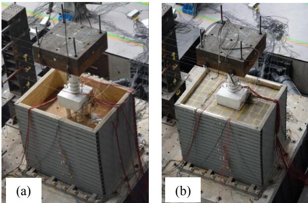
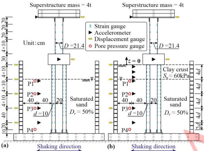
Figure 2 schematically shows the shake-table tests and associated instrumentations. The bridge specimen consists of a 2 \times 2 RC pile-group with pile diameters of 0.1\text{m} (d), center-to-center distances of 3d, and lengths of 19d. The pile tips stand on the base of the laminar box, fixed to a pre-embedded steel plate with four collars. The pile heads are connected through an RC cap with dimensions of 0.6\text{m} (length) \times 0.6\text{m} (width) \times 0.3\text{m} (height), supporting a single pier with a diameter of 0.214\text{m} (D) and a height of 1\text{m}. A 4-ton iron block is fixed to the pier head to represent the bridge superstructure. For the case without overburden crust, piles are embedded into a homogeneous saturated medium-dense sand layer with a thickness of 15d. In the other case, a 4d thickness clay crust layer (undrained shear strength S_u \approx 60\text{kPa}) overlies an almost identical sand layer (both cases with a relative density D_r \approx 50\%).
Before seismic excitations, white noise excitations are applied to obtain fundamental periods of the specimens; these are 0.51\text{s} and 0.38\text{s} for cases without and with the overburden crust, respectively. These periods generally fall into the common range of fundamental periods for ordinary multi-span girder bridges (0.26 \sim 0.65\text{s}) 11.
B. Structural and Soil Properties
Based on a survey of column and pile sections of bridges in practice, a longitudinal reinforcement ratio of 2\% and a transverse reinforcement ratio of 0.8\% are assigned to the specimens (both piers and piles). Specifically, for the pier, longitudinal reinforcements are provided by ten \phi 10\text{mm} rebars with a concrete cover of 2\text{cm}. Spiral \phi 6\text{mm} stirrups are arranged with an interval of 6\text{cm} for confinement. For the piles, six \phi 6\text{mm} rebars are assembled as longitudinal reinforcements with a concrete cover of 1\text{cm}. Confinement of the piles is supplied with spiral \phi 3.5\text{mm} stirrups with an interval of 4\text{cm}.
Shanghai sands are used to prepare a fully saturated soil profile. Tests on the particle size distribution of the sands indicate a poorly graded property with a mean grain size of 0.33\text{mm}, a coefficient of uniformity of 2.06, and maximum and minimum dry densities of 1.654\text{g/cm}^3 and 1.429\text{g/cm}^3, respectively.
To prepare a homogeneous saturated medium-dense sand deposit with D_r \approx 50\%, the rain-drop technique is used to prepare the liquefiable sand deposit layer by layer (10\text{cm} thickness for each layer). Details for the ground preparation procedure can be found in Wang et al. 10.
C. Instrumentation
Figure 2 illustrates the instrumentation of the shake-table tests. Various sensors, including accelerometers, displacement, strain, and pore pressure gauges, are adopted to obtain the excess pore pressure ratio, acceleration, and curvature demands during the test.
D. Adopted Ground Motion
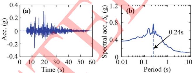
This paper presents the results of shake-table tests under the Chi-Chi 0.3g motion, originally obtained from the 1999 Chi-Chi Earthquake. Figure 3 shows its acceleration time history and corresponding acceleration spectrum. This ground motion contains significant high-frequency content, with a predominant period of 0.24\text{s}.
III. TEST RESULT INTERPRETATION
A. Excess Pore Pressure Ratio
Figure 4 compares excess pore pressure ratio (r_u) results at different locations between the two cases. r_u is defined in Equation (1):
where \Delta u is the recorded excess pore pressure and \sigma'_{v0} is the initial vertical effective stress.
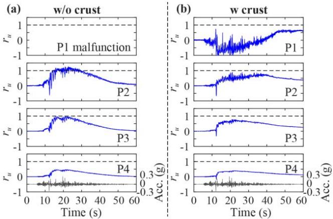
It can be found from Figure 4 that the sand liquefied under the Chi-Chi 0.3g ground motion for both cases (r_u mostly approaches 1.0). Moreover, r_u in the case without crust develops more rapidly than in the case with crust. This is attributed to the fact that the overburden crust significantly increases \sigma'_{v0}. In other words, the existence of overburden clay crust tends to impede the development of r_u. In addition, both cases show a dilation tendency (immediate reduction of r_u) during the development of r_u. For example, r_u at P2 for the case without crust drops at around 12\text{s}, even to a negative value, and recovers soon after. This fluctuation phenomenon occurs several times during the development of r_u.
B. Soil Acceleration
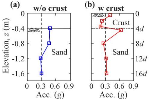
Figure 5 compares peak soil accelerations along depth between these two cases. It is clear that a generally amplified tendency is observed from the bottom of the laminar box to the soil surface for the case without crust. By contrast, an apparent maximum acceleration is observed at the crust-sand interface, due to large differences in strength and stiffness between these two soil layers.
C. Structural Acceleration
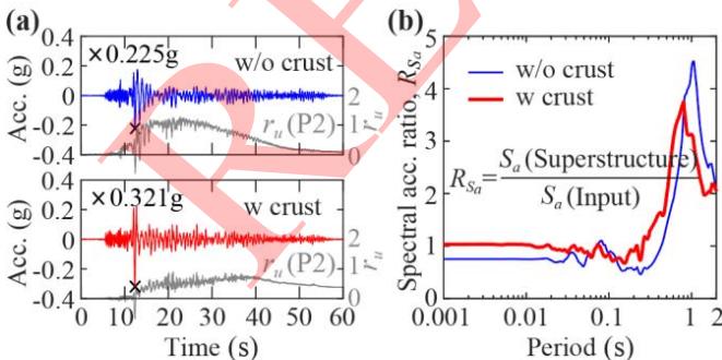
Figure 6 shows superstructure acceleration time histories and corresponding spectral acceleration ratios for these two cases under Chi-Chi 0.3g. From Figure 6(a), it is seen that peak accelerations occur at moments where the dilation tendency takes place. Figure 6(b) indicates that the case with crust exhibits a smaller predominant period as compared to the case without crust. Recalling the acceleration spectrum of the Chi-Chi 0.3g ground motion, the case with the smaller predominant period consequently displays a larger spectral acceleration ratio.
D. Curvature Distribution and Failure Mode
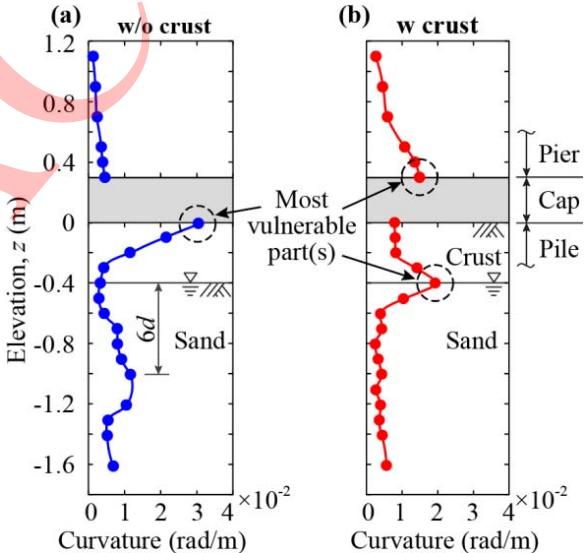
Figure 7 illustrates the curvature distributions along the pier and one of the piles. Note that pile group effects are not significantly detected for the studied pile center-to-center distance of 3d in liquefiable soil. The most vulnerable part for the case without crust occurs at the pile head above the soil surface. In addition, a potential underground damage area is detected at a depth around 6d. By contrast, in the case with crust, curvature demand at the bottom of the pier significantly increases, since the crust improves the lateral stiffness of the bridge specimen, leading to a smaller fundamental period that triggers larger demand at the pier. For the pile portion, the curvature demand at the pile head decreased significantly, while that at the crust-sand interface increased. The former is because the rotation of the pile head is restrained by the crust. The latter is attributed to the larger differences in lateral resistance and stiffness between the crust and the sand. In general, it can be concluded that the crust can transfer seismic damage from pile heads to the piles at the crust-sand interface and the pier bottoms.
IV. CONCLUSIONS
This paper presents the results of a pair of shake-table tests where 2 \times 2 pile-group-supported bridge specimens are embedded into liquefiable soil deposits with or without overburden clay crust. It is found that the overburden crust can significantly affect the failure modes by transferring damage from pile heads to the piles at the crust-sand interface and the pier bottoms.
ACKNOWLEDGEMENTS
This work is supported by NSFC (Grant No. 51778469), China Postdoctoral Science Foundation, and Fundamental Research Funds for the Central Universities.
B. R. Cox et al., "Liquefaction at strong motion stations and in Urayasu City during the 2011 Tohoku-Oki Earthquake," Earthq. Spectra, vol. 29, no. S1, pp. S55-S80, 2013. ↩
S. J. Brandenberg, R. W. Boulanger, B. L. Kutter, and D. Chang, "Behavior of pile foundations in laterally spreading ground during centrifuge tests," J. Geotech. Geoenviron. Eng., vol. 131, no. 11, pp. 1378-1391, 2005. ↩
L. Su, L. Tang, X. Ling, C. Liu, and X. Zhang, "Pile response to liquefaction-induced lateral spreading: A shake-table investigation," Soil Dyn. Earthq. Eng., vol. 82, pp. 196-204, 2016. ↩
R. Motamed, I. Towhata, T. Honda, K. Tabata, and A. Abe, "Pile group response to liquefaction-induced lateral spreading: E-Defense large shake table test," Soil Dyn. Earthq. Eng., vol. 51, no. 8, pp. 35-46, 2013. ↩
X. Wang, F. Luo, Z. Su, and A. Ye, "Efficient finite-element model for seismic response estimation of piles and soils in liquefied and laterally spreading ground considering shear localization," Int. J. Geomech., vol. 17, no. 6, pp. 06016039, 2017. ↩
X. Wang, A. Shafieezadeh, and A. Ye, "Optimal intensity measures for probabilistic seismic demand modeling of extended pile-shaft-supported bridges in liquefied and laterally spreading ground," Bull. Earthq. Eng., vol. 16, no. 1, pp. 229-257, 2018. ↩
X. Wu, L. Sun, S. Hu, and L. Fan, "Development of laminar shear box used in shaking table test," J. Tongji Univ., vol. 30, no. 7, p. 781-85 (in Chinese), 2002. ↩
X. Gao, X. Ling, L. Tang, and P. Xu, "Soil-pile-bridge structure interaction in liquefying ground using shake table testing," Soil Dyn. Earthq. Eng., vol. 31, no. 7, pp. 1009-1017, 2011. ↩
L. Tang and X. Ling, "Response of a RC pile group in liquefiable soil: A shake-table investigation," Soil Dyn. Earthq. Eng., vol. 67, pp. 301-315, 2014. ↩
X. Wang, A. Ye, A. Shafieezadeh, and J. Li, "Shallow-Layer p-y relationships for microplates embedded in saturated medium dense sand using quasi-static test," Geotech. Test. J., vol. 41, no. 1, pp. 20160289, 2018. ↩ ↩
R. K. Goel, "Earthquake characteristics of bridges with integral abutments," J. Struct. Eng., vol. 123, no. 11, pp. 1435-1443, 1997. ↩